Mixer with swirl box for a vehicle exhaust system

Active Publication Date: 2018-06-12
FAURECIA EMISSIONS CONTROL TECH GERMANY
View PDF18 Cites 10 Cited by
  • Summary
  • Abstract
  • Description
  • Claims
  • Application Information

AI Technical Summary

Benefits of technology

[0003]In one exemplary embodiment, a vehicle exhaust system includes a mixer and a doser that sprays a reducing agent into the mixer to be thoroughly mixed with engine exhaust gases prior to introduction of the mixture into a downstream exhaust component. The mixer includes an upstream baffle with at least one inlet opening and a downstream baffle with at least one outlet opening. An outer peripheral wall surrounds the upstream and downstream baffle and includes a doser opening. A doser is mounted at the doser opening and is configured to spray a reducing agent into an area between the upstream and downstream baffles. A deflector is positioned between the inlet opening and the doser opening to protect spray at the doser opening from direct impact with exhaust gas from the inlet opening, and an impactor is positioned adjacent to the deflector and faces the doser opening.
[0009]In another exemplary embodiment, a vehicle exhaust system includes a mixer having an inlet end configured to receive engine exhaust gases and an outlet end configured to conduct engine exhaust gases to a downstream exhaust component. The mixer includes an upstream baffle with at least one inlet opening and a downstream baffle with an outlet opening, with the upstream and downstream baffles being surrounded by an outer peripheral wall. A doser is configured to spray a reducing agent into the mixer. The doser defines a central doser axis and is mounted at a doser opening within the outer peripheral wall. A deflector is positioned within the mixer between the inlet opening and the doser opening to protect spray at the doser opening from direct impact with exhaust gas introduced into the mixer via the inlet opening. An impactor is positioned within the mixer such that a portion of the impactor intersects the doser axis.

Problems solved by technology

This is disadvantageous when using smaller droplet sizes as the droplets tend not to penetrate sufficiently into the exhaust flow.

Method used


Image

  • Mixer with swirl box for a vehicle exhaust system
  • Mixer with swirl box for a vehicle exhaust system
  • Mixer with swirl box for a vehicle exhaust system

Examples


Embodiment Construction

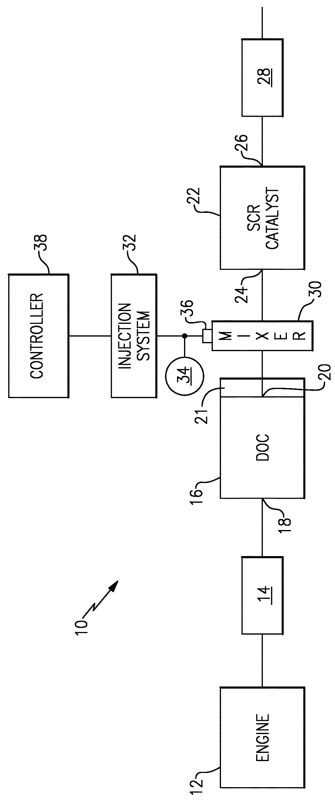
[0025]FIG. 1 shows a vehicle exhaust system 10 that conducts hot exhaust gases generated by an engine 12 through various upstream exhaust components 14 to reduce emission and control noise as known. The various upstream exhaust components 14 can include one or more of the following: pipes, filters, valves, catalysts, mufflers etc.

[0026]In one example configuration, the upstream exhaust components 14 direct exhaust gases into a diesel oxidation catalyst (DOC) 16 having an inlet 18 and an outlet 20. Downstream of the DOC 16 there may be a diesel particulate filter (DPF) 21 that is used to remove contaminants from the exhaust gas as known. Downstream of the DOC 16 and optional DPF 21 is a selective catalytic reduction (SCR) catalyst 22 having an inlet 24 and an outlet 26. The outlet 26 communicates exhaust gases to downstream exhaust components 28. Optionally, component 22 can comprise a catalyst that is configured to perform a selective catalytic reduction function and a particulate f...


PUM

PropertyMeasurementUnit
volumeaaaaaaaaaa
pressureaaaaaaaaaa
areaaaaaaaaaaa

Abstract

A vehicle exhaust system includes a mixer and a doser that sprays a reducing agent into the mixer to be thoroughly mixed with engine exhaust gases prior to introduction of the mixture into a downstream exhaust component. The mixer includes an upstream baffle with at least one inlet opening and a downstream baffle with at least one outlet opening. An outer peripheral wall surrounds the upstream and downstream baffle and includes a doser opening. A doser is mounted at the doser opening and is configured to spray a reducing agent into an area between the upstream and downstream baffles. A deflector is positioned between the inlet opening and the doser opening to protect spray at the doser opening from direct impact with exhaust gas from the inlet opening, and an impactor is positioned adjacent the deflector and faces the doser opening.

Description

BACKGROUND OF THE INVENTION[0001]An exhaust system conducts hot exhaust gases generated by an engine through various exhaust components to reduce emissions and control noise. The exhaust system includes an injection system that injects a diesel exhaust fluid (DEF) or a reducing agent, such as a solution of urea and water for example, upstream of a selective catalytic reduction (SCR) catalyst. A mixer is positioned upstream of the SCR catalyst and mixes engine exhaust gases and products of urea transformation.[0002]The doser typically sprays the urea into the exhaust stream. In one known configuration, the doser is mounted to an outer peripheral surface of the mixer and directs the spray radially inwardly toward a center of the mixer. The spray tends to have a larger droplet size in order to provide a high spray penetration such that the droplets are spread across the entire exhaust cross-section. However, smaller droplet sizes are preferred as droplets with smaller diameters evapora...

Claims


Application Information

Patent Timeline
Patent Type & Authority Patents(United States)
IPC IPC(8): B01D50/00F01N3/20B01D53/94F01N3/28
CPCF01N3/2066B01D53/9431F01N3/208F01N3/2892Y02T10/24F01N2240/20F01N2610/02F01N2610/1453Y02A50/20Y02T10/12B01F23/2132B01F2025/931B01F25/25B01F25/3141B01F25/4314
Inventor ALANO, EDUARDOSCOTT, JONATHAN
Owner FAURECIA EMISSIONS CONTROL TECH GERMANY
Why Eureka
Try Eureka