Rotary electric machine control device

a control device and electric machine technology, applied in control systems, electrical equipment, electronic commutators, etc., can solve the problems of inability to accurately detect the position of the pole, the pulse width may be reduced, and the detection error, so as to reduce the reliability of determination, accurate detection of the magnetic pole position, and high accuracy

Active Publication Date: 2018-06-12
AISIN AW CO LTD
View PDF7 Cites 9 Cited by
  • Summary
  • Abstract
  • Description
  • Claims
  • Application Information

AI Technical Summary

Benefits of technology

[0011]performs dead-time compensation in which a start point and an end point of a control pulse for switching elements that compose the inverter are adjusted to reduce an error in AC output due to a dead-time period, in which both an upper switching element and a lower switching element, of the switching elements, that compose an arm for one phase of the inverter are controlled into an off state, compared to that for a case where the control pulse is a reference pulse; and
[0014]In order to accurately detect the magnetic pole position through sensorless control, it is useful to execute the dead-time compensation. To perform the dead-time compensation, however, it is generally necessary to determine the polarity of the phase current of AC power. Here, in the case where the amplitude of the phase current is small and the wave height of the phase current is close to the center of amplitude of the phase current, such as in the case where the rotary electric machine is driven by low torque, a high accuracy may be required for the determination of the polarity of the phase current, or the reliability of the determination may be lowered depending on the determination accuracy. In the present configuration, the current command is decided such that the armature current becomes equal to or more than the lower-limit current. The magnitude of the amplitude of the phase current can be secured by restraining a reduction in armature current. That is, the amplitude of the phase current can be secured such that the polarity of the phase current can be determined sufficiently. In the case where the magnitude of the armature current is equal to or more than the lower-limit current, the armature current is not restrained. Thus, the operation efficiency of the rotary electric machine is affected only in the case where the magnitude of the armature current is less than the lower-limit current. Thus, with the present configuration, it is possible to provide a sensorless magnetic pole position detection technique that allows the magnetic pole position of a rotary electric machine to be electrically derived accurately by reducing a voltage error due to a dead time while suppressing the influence on the operation efficiency of the rotary electric machine.

Problems solved by technology

Because of the dead time, the actual effective pulse width may be reduced with respect to the effective pulse width of a switching pulse based on a modulation command, and an error from a command value may be caused in output voltage obtained after conversion from DC power to AC power.
The error may affect electrical detection of the magnetic pole position to cause a detection error.
When the proportion of the period in which the phase currents have a value close to the center of amplitude (zero) to the cycle of the phase currents is large, such as in the case where the amplitude of the phase currents is small, however, the magnetic pole position cannot be detected accurately for a long period, as a result of which the accuracy in detecting the magnetic pole position may be lowered.
With this method, however, torque ripple tends to be increased, because the current is set to an advanced phase and a delayed phase.

Method used


Image

  • Rotary electric machine control device
  • Rotary electric machine control device
  • Rotary electric machine control device

Examples


embodiment

Overview of Embodiment

[0075]The overview of the rotary electric machine control device (1) according to the embodiment described above will be briefly described below.

[0076]In one aspect, the rotary electric machine control device (1):

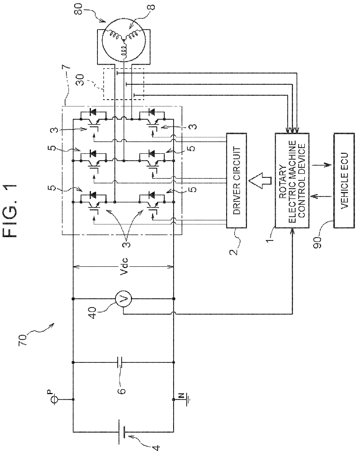
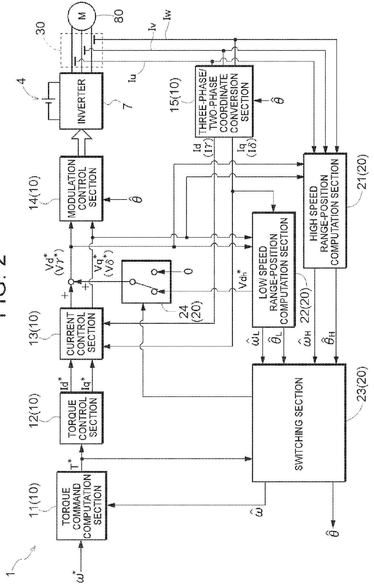
[0077]controls a rotary electric machine (80) that includes a rotor in which a permanent magnet is disposed and that is driven via an inverter (7) that performs power conversion between AC power and DC power;

[0078]detects a magnetic pole position (θ) of the rotor through sensorless control;

[0079]performs current feedback control, using the magnetic pole position (θ), on the basis of a deviation between a current command (Id*, Iq*) and a feedback current from the rotary electric machine (80) in a d-q-axis vector coordinate system defined by a d-axis which extends in a direction of a magnetic field generated by the permanent magnet and a q-axis which is orthogonal to the d-axis;

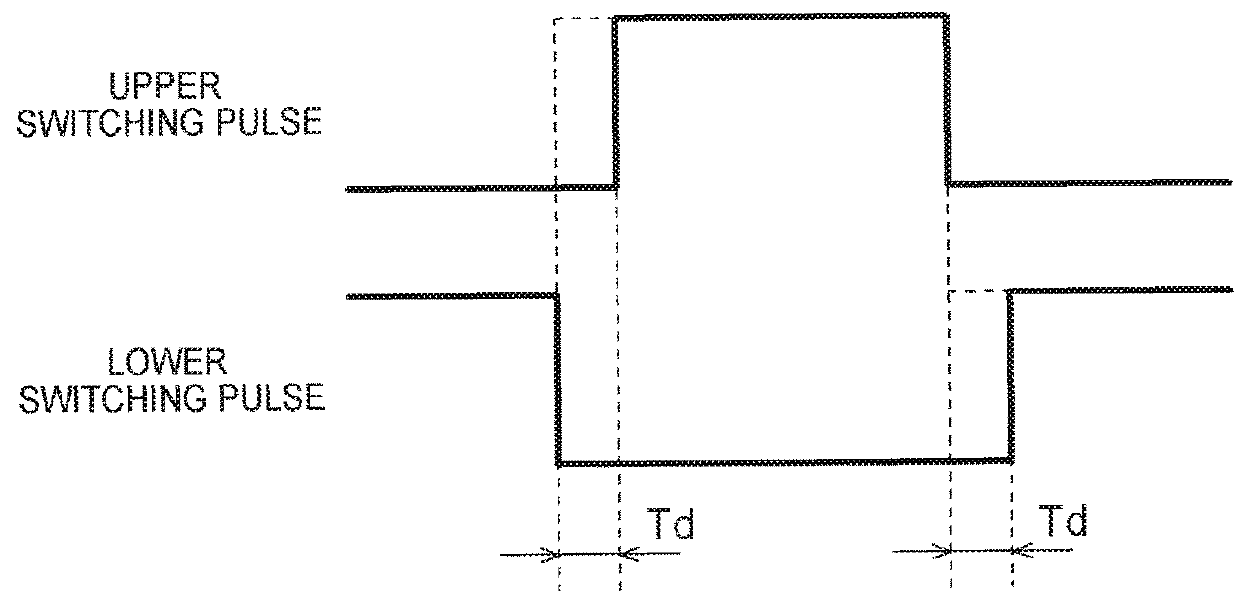
[0080]performs dead-time compensation in which a start point and an end point...


PUM


Abstract

The magnetic pole position of a rotary electric machine is electrically derived accurately by reducing a voltage error due to a dead time while suppressing the influence on the operation efficiency of the rotary electric machine. A control device performs dead-time compensation, and performs current feedback control in a d-q-axis vector coordinate system using a magnetic pole position computed on the basis of an induced voltage produced by rotation of a rotor or on the basis of a response component to a high-frequency observation signal applied to the rotary electric machine. In the case where the rotary electric machine is controlled by deciding current commands Id*, Iq* in the d-q-axis vector coordinate system, the rotary electric machine control device controls the rotary electric machine such that the magnitude of an armature current Ia becomes equal to or more than a lower-limit current Ia_min prescribed in advance.

Description

I. TECHNICAL FIELD[0001]Embodiments of the present disclosure relate to a rotary electric machine control device that controls a rotary electric machine that includes a rotor in which a permanent magnet is disposed and that is driven via an inverter that performs power conversion between AC power and DC power.BACKGROUND ART[0002]A control method called vector control is known as a control method for a rotary electric machine, e.g. an interior permanent magnet synchronous motor (IPMSM). In the vector control, feedback control is performed by subjecting motor currents that flow through stator coils of the motor to a coordinate conversion into vector components for a d-axis, which extends in the direction of a magnetic field generated by a permanent magnet disposed in a rotor, and a q-axis, which is orthogonal to the d-axis. For the coordinate conversion, it is necessary to accurately detect the position of the rotor (magnetic pole position). A rotation sensor such as a resolver is oft...

Claims


Application Information

Patent Timeline
Patent Type & Authority Patents(United States)
IPC IPC(8): H02P23/03H02P27/08H02P6/18
CPCH02P23/03H02P27/08H02P6/18H02P27/06H02P21/18
Inventor SHIMADA, ARINORIMIYAZAKI, MASASHISAHA, SUBRATANISHIMURA, KEISUKEIWATSUKI, KEN
Owner AISIN AW CO LTD
Why Eureka
Try Eureka