

Gold-tin solder suitable for self-aligning applications
- Summary
- Abstract
- Description
- Claims
- Application Information
AI Technical Summary
Benefits of technology
Problems solved by technology
Method used
Image

Examples
Embodiment Construction
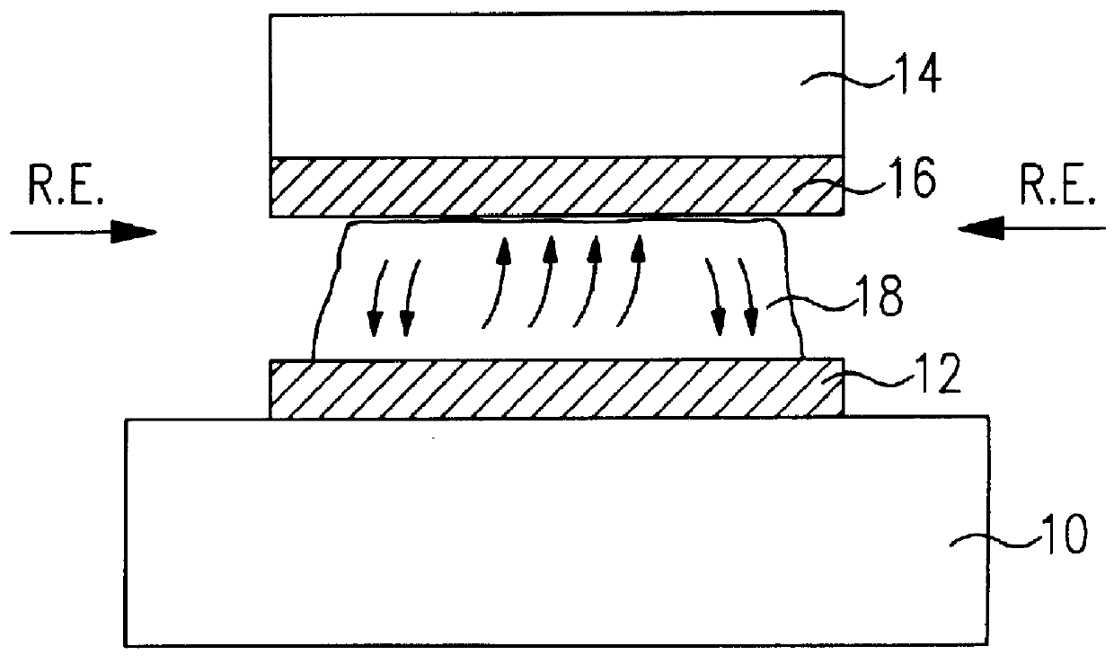
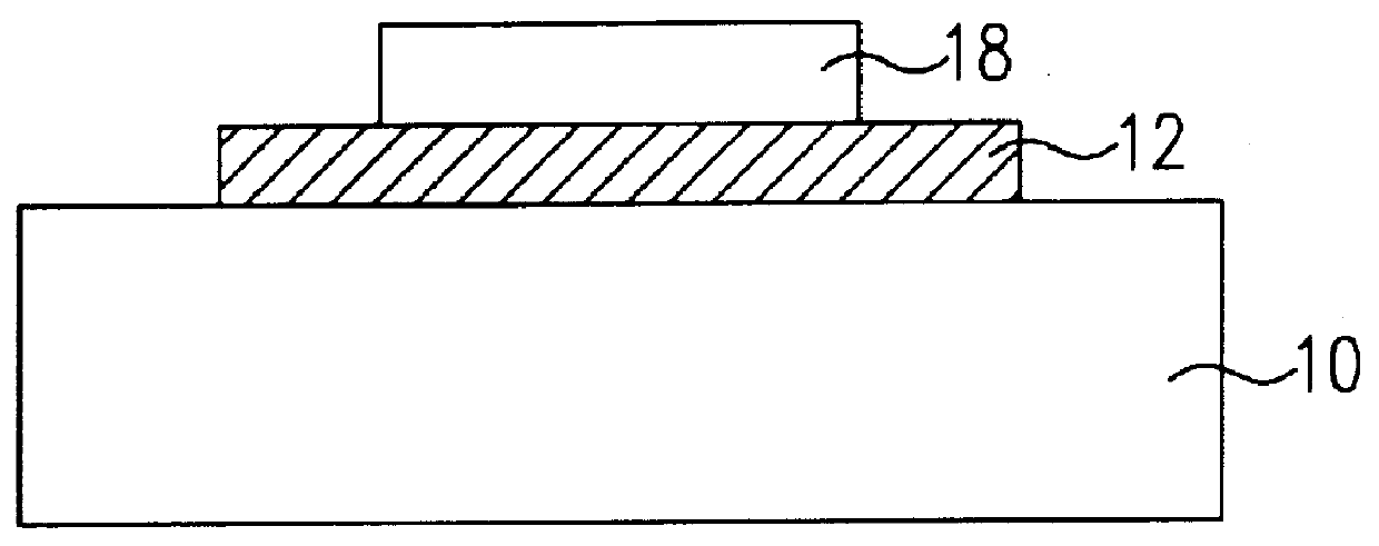
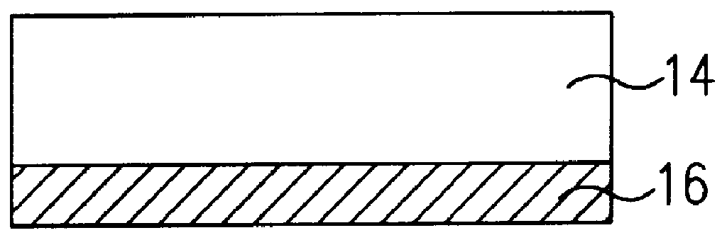
An exemplary process for providing self-aligned solder attachment of a pair of components is illustrated in FIGS. 1-3. The inventive bonding process will be particularly described in association with the self-aligned attachment of an LED to a bond pad. However, it is to be understood that the tin-rich solder of the present invention is ubiquitous in nature and can be utilized within virtually any desired soldering process. Referring back to FIG. 1, a device submount 10, which may be formed of silicon, is illustrated as including a bond pad 12. Conventionally, bond pad 12 is formed of a highly conductive material and, in particular, may comprise a tri-layer structure of titanium, platinum and gold. Gold, in general, is often used for bond pads due to its inert nature and relatively high conductivity. A device 14, such as an LED, is illustrated in FIG. 1 as positioned above bond pad 12. Device 14 also includes a conductive layer 16 (which may also comprise a tri-level, or gold plated ...
PUM
| Property | Measurement | Unit |
|---|---|---|
| Percent by mass | aaaaa | aaaaa |
| Percent by mass | aaaaa | aaaaa |
| Angle | aaaaa | aaaaa |
Abstract
Description
Claims
Application Information