Droplet deposition apparatus

a droplet and droplet technology, applied in the field ofpulsed droplet deposition apparatus, can solve the problems of inability to provide very high reliability and extended life, inability to produce ink deposits, and inability to meet the requirements of high-quality droplet deposition, and achieve the effect of economic manufactur

Inactive Publication Date: 2000-04-25
XAAR TECH LTD
View PDF48 Cites 29 Cited by
  • Summary
  • Abstract
  • Description
  • Claims
  • Application Information

AI Technical Summary

Benefits of technology

Broadly, it is an object of this invention to provide improved multi-channel pulse droplet deposition apparatus operating at low energy levels and providing relatively large numbers of channels per unit length whether transverse to or parallel with the direction of paper movement, or both. It is a further object of this invention to provide such apparatus which is economic in manufacture.
The present invention in one aspect consists in a high density multi-channel array, electrically pulsed droplet deposition apparatus, comprising a multiplicity of parallel droplet liquid channels, mutually spaced in an array direction normal to the length of channels, each of said channels being separated from a like channel by a side wall which is transversely displaceable in respective opposite senses and which extends in the lengthwise direction of the channels, and in a direction which is both normal to said lengthwise direction and normal to the array direction, respective nozzles opening into said channels for ejection therefrom of droplets of liquid, connection means for connecting said channels to a source of droplet deposition liquid and electrically actuable means located in relation to said channels for effecting in each channel selected for actuation, transverse displacement generally parallel to said array direction of said transversely displaceable side wall of said selected channel, to cause change of pressure in said selected channel to effect droplet ejection from the nozzle opening thereinto.

Problems solved by technology

First, the thermal mode of operation is inefficient and typically requires 10 to 100 times the energy to produce an ink droplet as compared with known piezo-electric printheads.
Second, difficulties are found in providing the very high levels of reliability and extended lifetimes which are necessary in an ink jet printhead.
For example, thermally operated printheads have a tendency for ink deposits to form on the heating electrodes.
Thermal stress cracks and element burn-out, as well as cavitation erosion, have also proved difficult to eliminate.
Third, only ink specifically developed to tolerate thermal cycling can be used and suitable ink formulations often proved to be of low optical density compared with conventional inks.
However, the existing proposals have not achieved the levels of printing resolution that are desired.
In terms of effective resolution, and by this is meant the density at which the droplets can be deposited upon paper, such nozzle density is for many applications insufficient.
It does not, for example, enable a transverse line to be printed with ink droplets that are indistinguishable by the eye at normal reading distance.
As will be understood, this introduces significant mechanical and control complexities, and is not felt to be advantageous.
The provision of delay circuitry adds to manufacturing costs by an amount which typically increases with the amount of delay required.

Method used


Image

  • Droplet deposition apparatus
  • Droplet deposition apparatus
  • Droplet deposition apparatus

Examples


Embodiment Construction

In the drawings, like parts have been accorded the same numerical references.

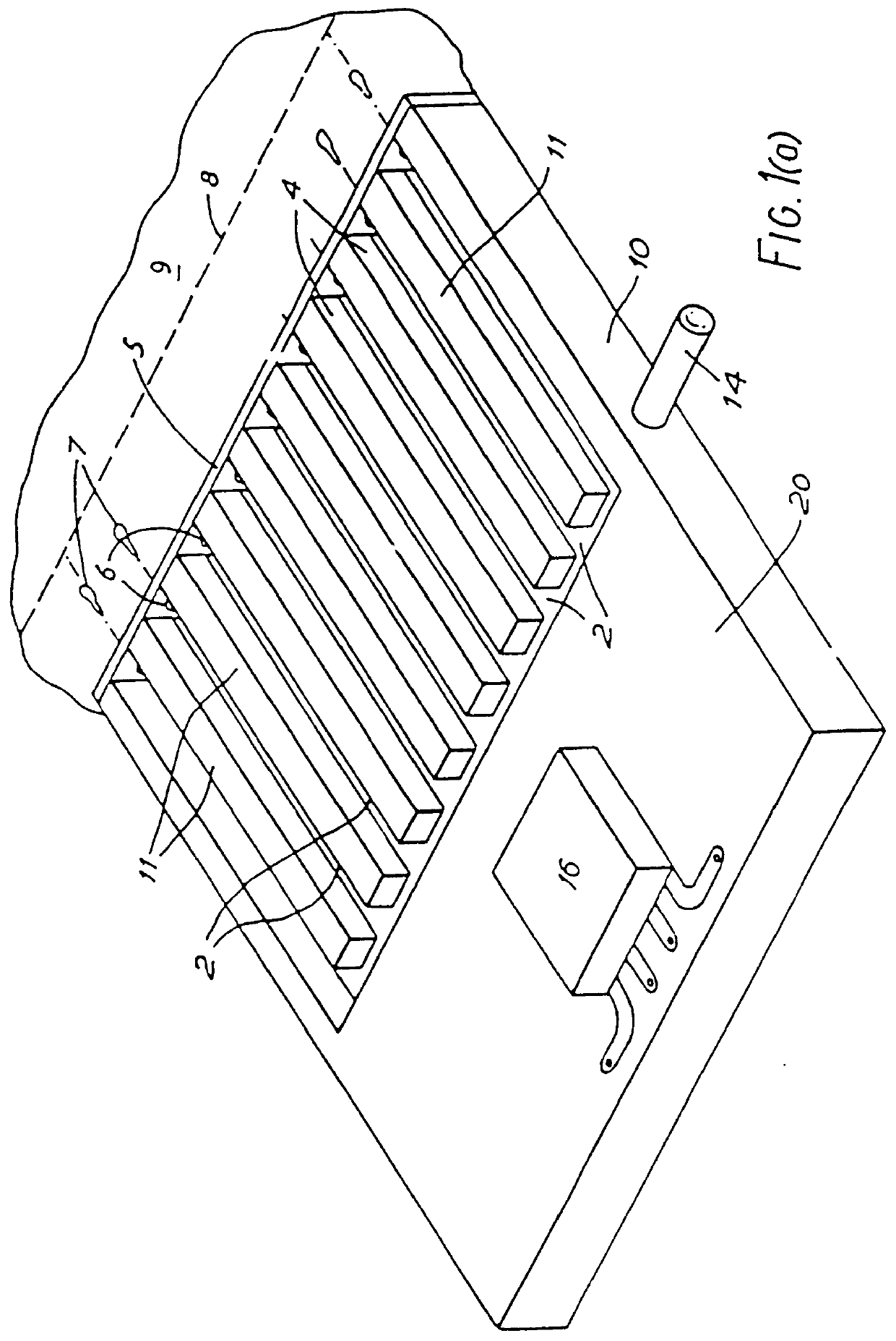
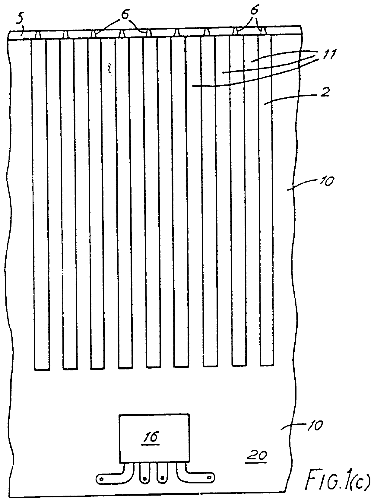
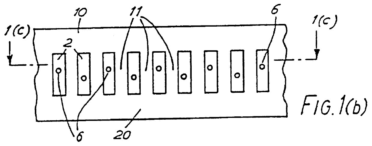
Referring first to FIGS. 1(a), 1(b) and 1(c), a planar high-density array, drop-on-demand ink jet printer comprises a printhead 10 formed with a multiplicity of parallel ink channels 2, nine only of which are shown and the longitudinal axes of which are disposed in a plane.

By "high-density array" in this context is meant an array in which the ink channel density along a line intersecting the channel axes perpendicularly, is at least two per millimetre. The channels 2 contain ink 4 and terminate at corresponding ends thereof in a nozzle plate 5 in which are formed nozzles 6, one for each channel. Ink droplets 7 are ejected on demand from the channels 2 and deposited on a print line 8 of a print surface 9 between which and the printhead 10 there is relative motion normal to the plane of the channel axes.

The printhead 10 has a planar base part 20 in which the channels 2 are cut or otherwise formed so as to ext...


PUM


Abstract

A pulsed droplet ink jet printer has relatively long thin ink channels extending in parallel between an ink manifold 13, and a nozzle plate 5 providing a nozzle 6 for each channel. Side walls 11 may be formed substantially entirely of piezo-electric material so as to be displaceable transversely into a selected channel on the application of an electric field. This transverse displacement produces an acoustic wave in the channel which results in the ejection of an ink droplet. The side walls may deflect in shear mode to a cross-section of chevron formation. Usefully, it is arranged that both side walls adjoining the selected channel are displaced inwardly of the channel to cooperate in droplet ejection. Under this arrangement, the channels are assigned alternately to first and second groups of channels, only one group of channels being capable of actuation at any one instant. The nozzles associated with the respective groups of channels may be offset so as to compensate for the time delay in actuation of channels in the first and second groups.

Description

BACKGROUND OF THE INVENTIONThis invention relates to pulsed droplet deposition apparatus and more particularly to such apparatus including a plurality of droplet deposition channels. Typical of this kind of apparatus are multi-channel pulsed droplet ink jet printers, often also referred to as "drop-on-demand" ink jet printers.An existing technology for the production of multi-channel drop-on-demand ink jet printers is known from, for example, U.S.-A-3,179,042; GB-A-2 007 162 and GB-A-2 106 039. These patent specifications disclose thermally operated printheads which, in response to an electrical input signal, generate a heat pulse in selected ink channels to develop a vapour bubble in the ink of those selected channels. This in turn generates a pressure pulse having the pressure and time characteristics appropriate for the ejection of an ink droplet through a nozzle at the end of the channel.Thermally operated printheads of this nature possess a number of significant disadvantages. ...

Claims


Application Information

Patent Timeline
Patent Type & Authority Patents(United States)
IPC IPC(8): B41J2/045B41J2/04B41J2/16H01L41/09B41J2/055B41J2/14H01L41/08
CPCB41J2/04525B41J2/04543B41J2/04581B41J2/04588B41J2/14209B41J2/1609B41J2/1632B41J2/1634B41J2/1642B41J2/1643B41J2/1623B41J2202/10B41J2002/041B41J2002/14225
Inventor MICHAELIS, A. JOHNPATON, ANTHONY D.TEMPLE, STEPHENBARTKY, W. SCOTT
Owner XAAR TECH LTD
Why Eureka
Try Eureka