Method for use of liquid/vapor ammonia absorption systems in unitary HVAC systems

a technology of liquid/vapor ammonia absorption and unitary hvac system, which is applied in the operation mode of machines, refrigeration machines, light and heating apparatus, etc., can solve the problem that a good portion of heat is generated in the absorber of the absorption system, and achieve the effect of facilitating the switching of the evaporator

Inactive Publication Date: 2000-05-09
ROCKY RES
View PDF7 Cites 26 Cited by
  • Summary
  • Abstract
  • Description
  • Claims
  • Application Information

AI Technical Summary

Benefits of technology

The separation of indoor and outdoor unit heat transfer interface not only eliminates the need for a secondary brine between the sorption cycle and the outdoor coil, but also allows for use of a more efficient brine for interface with the indoor coil only since the operating temperature range of the indoor coil is limited to about 33.degree. F. to 140.degree. F. Freeze point protection is only required for safety without need to operate at low temperatures, and less viscous fluids can be employed. It is also possible to use an environmentally acceptable phase change material, e.g. HFC, for heat transfer in this secondary loop even though such material may not be generally suitable in vapor compression processes.
a reversing valve means, e.g. four way valve, to facilitate the switching of evaporator and condenser function,

Problems solved by technology

While vapor compression systems are designed to exchange useful heat via condenser and evaporator only, absorption systems have the complication that a good portion of the heat is generated in the absorber.
It is also possible to use an environmentally acceptable phase change material, e.g. HFC, for heat transfer in this secondary loop even though such material may not be generally suitable in vapor compression processes.

Method used


Image

  • Method for use of liquid/vapor ammonia absorption systems in unitary HVAC systems
  • Method for use of liquid/vapor ammonia absorption systems in unitary HVAC systems
  • Method for use of liquid/vapor ammonia absorption systems in unitary HVAC systems

Examples


Embodiment Construction

In FIGS. 3-8, the solution flow pathway including solution pump, absorber heat exchanger, generator heat exchanger, as well as any GAX fluid pathway using all or a portion of the liquor or a separate heat exchange loop is intentionally omitted as the present invention is not limited to any specific GAX or non-GAX cycle configuration.

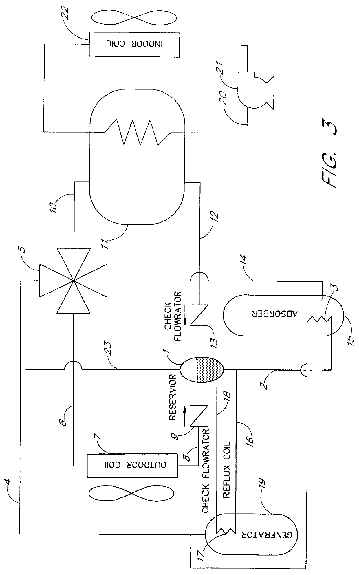
FIG. 3 shows a basic cycle apparatus according to this invention. The main feature of this cycle is that phase change ammonia heat transfer is used to combine all heat rejection from the cycle into a single fluid stream so that a conventional reversing valve (4-way valve) can be used to switch between heating and cooling modes.

Condensed ammonia is collected in a reservoir 1. Liquid ammonia is allowed to flow from the reservoir through conduit 2 to a heat transfer coil 3 in the absorber 15. In this coil, ammonia is fully or partially vaporized. Vapor, with possibly some entrained liquid, flows from coil 3 through conduit 4 to reversing valve 5. In cooling...


PUM


Abstract

A liquid vapor absorption system comprises: one or more absorbers, one or more generators, and a fluid loop for directing refrigerant absorption fluid between the absorbers and generators, heat exchangers for selectively functioning as an evaporator or a condenser and cooperating with an indoor coil for recovering thermal energy, a reservoir for condensed refrigerant, a phase-change thermosyphon loop for directing condensed refrigerant from the reservoir to the heat exchange section of an absorber for removing heat of absorption, and a reversing valve means for selectively directing gaseous refrigerant to the heat exchangers functioning as a condenser, and for simultaneously directing gaseous refrigerant from the heat exchangers functioning as an evaporator to the absorber.

Description

BACKGROUND OF THE INVENTIONThe invention relates to absorption beat pump systems and particularly to liquid / vapor absorption systems using ammonia refrigerant and water, salt, or salt and water absorbents. Thermal efficiencies of such systems have been improved during the past years by use of innovative heat recuperation within the absorber as well as between the one or more absorbers and the generator. Such improvements use absorber heat exchangers as well as generator / absorber heat exchange facilitated by use of the rich or weak absorption working fluid or by separate heat exchange loop. Detailed descriptions on the use and implementation can be found in U.S. Pat. Nos. 4,311,019, 5,024,063, 5,271,235, 5,367,884; R. J. Modahl and F. C. Hayes, "Evaluation of Commercial Advanced Absorption Heat Pump Breadboard", The Trane Company pp. 117-125, 1988, as well as numerous other publications. While all of the above improvements are intended to increase the rating or seasonal thermal effic...

Claims


Application Information

Patent Timeline
IPC IPC(8): F25B15/02F25B29/00
CPCF25B15/02F25B29/006Y02B30/62F25B2315/006Y02A30/27
Inventor ROCKENFELLER, UWEKIROL, LANCE
Owner ROCKY RES
Why Eureka
Try Eureka