Check valve

a check valve and valve body technology, applied in the field of valves, can solve the problems of not providing the increased power boost desired to implement the brakes or other subsystems, and achieve the effect of preventing back pressur

Inactive Publication Date: 2001-03-13
NYLONCRAFT INC
View PDF5 Cites 32 Cited by
  • Summary
  • Abstract
  • Description
  • Claims
  • Application Information

AI Technical Summary

Benefits of technology

This invention provides for a space-saving vacuum booster check valve located along a conduit between the air intake manifold and the brake booster. The check valve includes three or more ports connected by hoses to the air intake, block, and one or more vehicle subsystems. V

Problems solved by technology

Space limitations in the automobile engine compartment all but preclude the use of multiple valve-hose system, while the prior

Method used


Image

  • Check valve
  • Check valve
  • Check valve

Examples


Embodiment Construction

The preferred embodiment of the invention herein described is not intended to be exhaustive or to limit the invention to the precise form disclosed. It is chosen and described to explain the principles of the invention, and its application and practical use to enable others skilled in the art to follow its-teachings.

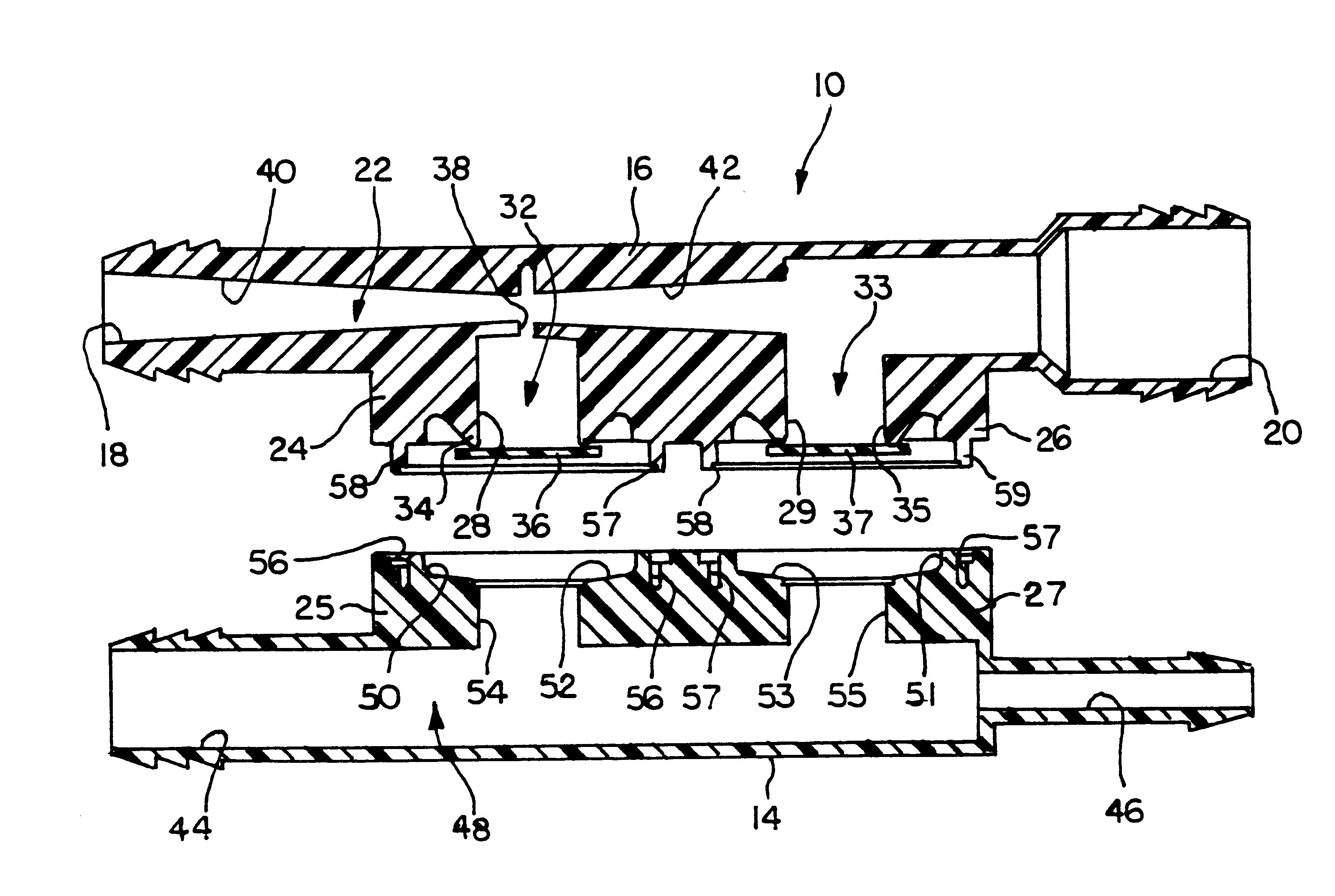
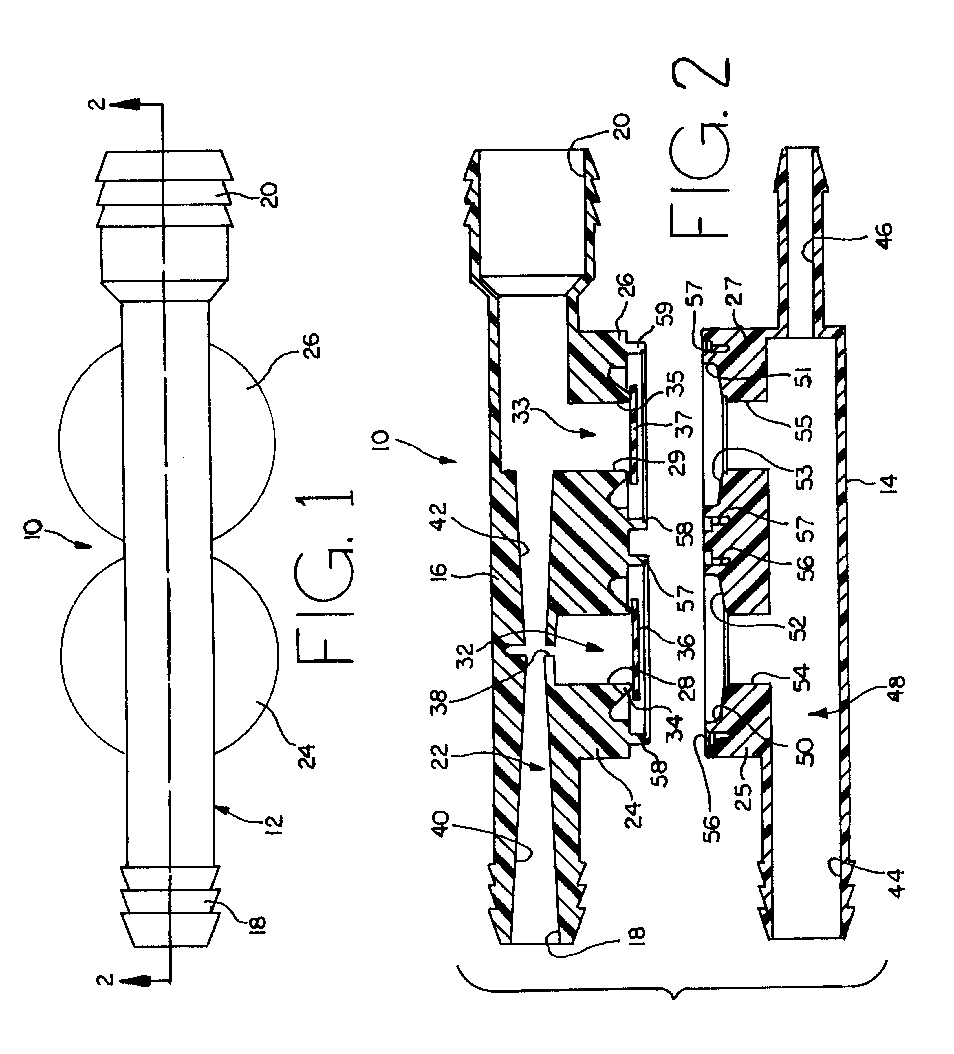
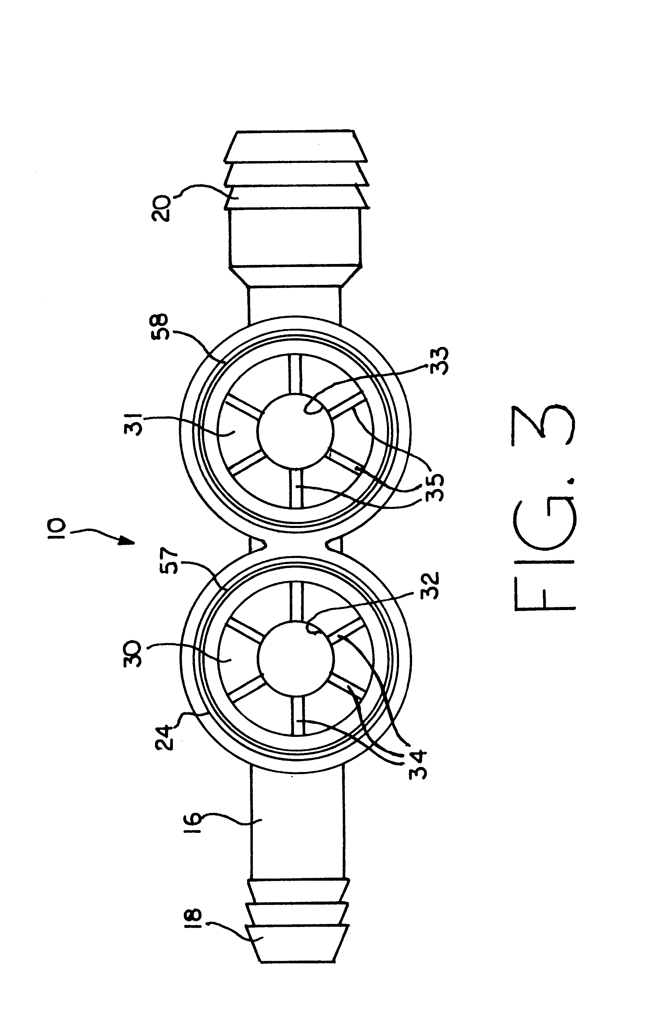
Referring now to the drawings, reference numeral 10 refers generally to the check valve of this invention. Check valve 10 is normally employed in an internal combustion engine in the air flow line between the engine block and the air intake port at the full mixing port, normally a carburetor or fuel injection port. For clarity, the engine, carburetor, hose connections, and subsystems are not shown, and it is understood that these ports are common to the internal combustion engines found in almost all vehicles.

The air flow system in the typical internal combustion engine operates on the principle that as the engine operates, a partial vacuum is created which pulls air thr...


PUM


Abstract

A check valve which is positioned in the vacuum air line of an internal combustion engine. The check valve includes a single-piece valve body having an outlet port and two or more inlet ports, with one outlet port located substantially in line with the inlet port and connected by a venturi tube. The second inlet port is separated from the main air flow line by the valve stem and a diaphragm which allows communication there between and prevents back pressure. The second inlet port communicates with the outlet port through the valve stem and a second venturi tube which provides a vacuum boost to a device, usually vehicle brakes, connected to the inlet.

Description

FIELD OF THE INVENTIONThis invention relates to valves, and will have special application to check valves used in internal combustion engines.BACKGROUND OF THE INVENTIONInternal combustion engines have long employed air flow conduits to provide vacuum assist for automobile subsystems, such as brakes, automatic transmissions and others. These systems often employed chick valves located along the air flow conduit to prevent subsystem back pressure from reaching the engine. A typical check valve of this sort is described in U.S. Pat. No. 3,889,710.Prior check valves employed either a continuous diameter airway or employed multiple valves and hoses to create a venturi effect and act as a vacuum booster for the subsystem to which it was associated. Space limitations in the automobile engine compartment all but preclude the use of multiple valve-hose system, while the prior art continuous diameter airways did not provide the increased power boost desired to implement the brakes or other s...

Claims


Application Information

Patent Timeline
IPC IPC(8): B60T17/00B60T17/04B60T17/02
CPCB60T17/02B60T17/04Y10S137/907Y10T137/2567Y10T137/87643
Inventor KLOOSTERMAN, KENNETH D.BARLOW, JOHN
Owner NYLONCRAFT INC
Why Eureka
Try Eureka