

Motion compensated prediction interframe coding system
- Summary
- Abstract
- Description
- Claims
- Application Information
AI Technical Summary
Benefits of technology
Problems solved by technology
Method used
Image

Examples
first embodiment
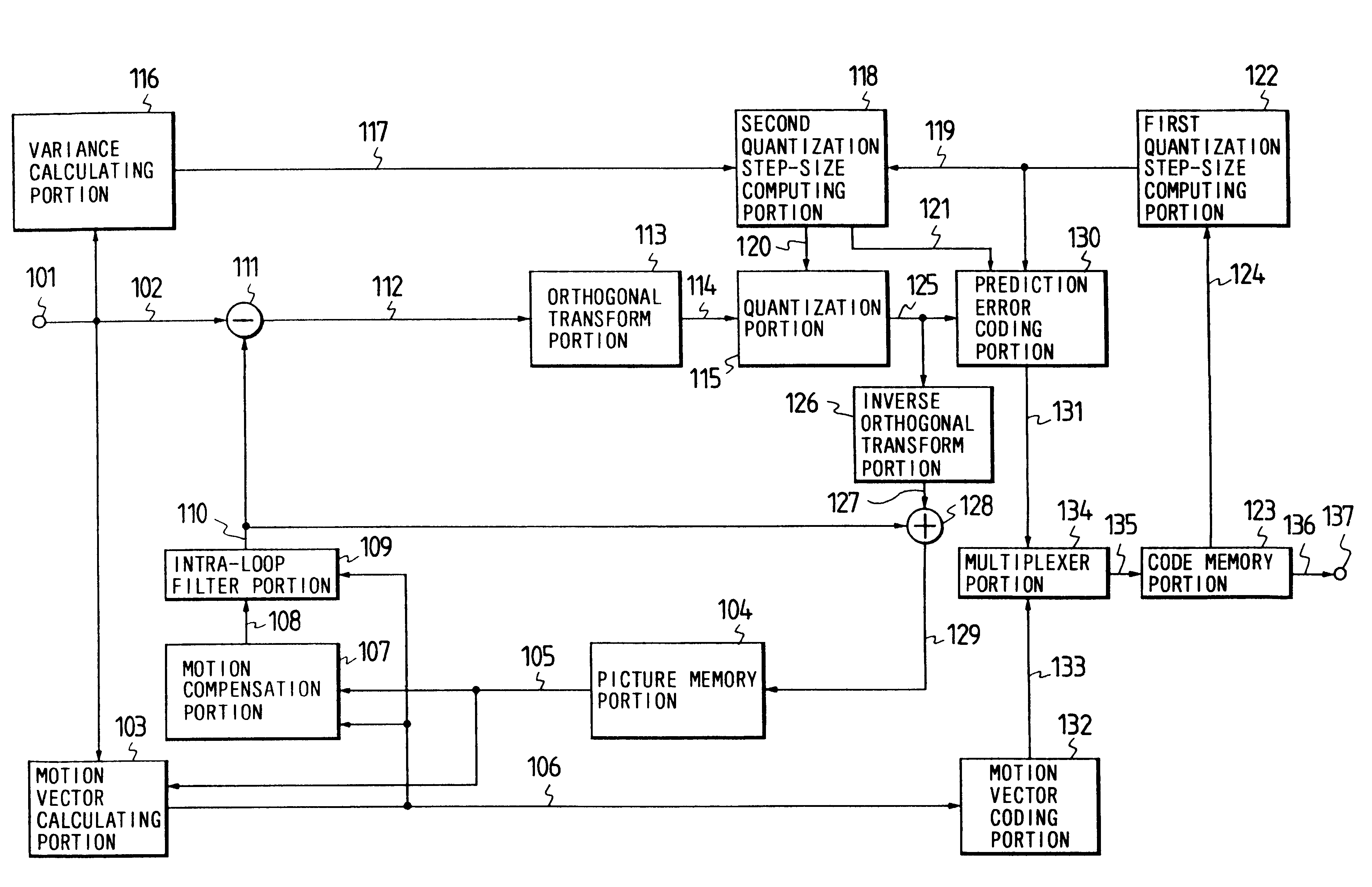
First, the present invention will be described hereinbelow with reference to FIG. 3.
In this figure, reference numeral 101 designates an input terminal from which television signals are inputted to the system; 103 a motion vector calculating portion for comparing a picture signal of a coding block of a current frame with a reproduced picture signal of a previous frame and calculating a motion vector; 104 a picture memory portion for storing reproduced picture signals of a current and previous frames; 107 a motion compensation portion for performing a motion compensation of the reproduced picture signals of the previous frame; 109 an intra-loop filter portion for performing two-dimensional lowpass filtering processing of a motion compensation predicting signal; 111 a prediction error evaluating portion for evaluating a prediction error by computing the difference between an original picture signal and a predictive signal of a coding block; 113 an orthogonal transform portion for perfo...
second embodiment
Next, the present invention will be described hereinbelow with reference to FIG. 4.
In this figure, reference numeral 201 designates an input terminal from which television signals are inputted to the system; 203 a motion vector calculating portion for comparing a picture signal of a coding block of a current frame with a reproduced picture signal of a previous frame and calculating a motion vector; 204 a picture memory portion for storing reproduced picture signals of a current and previous frames; 207 a motion compensation portion for performing a motion compensation of the reproduced picture signals of the previous frame; 209 a coding method selection portion for selecting a method of coding of a block from an interframe coding and interframe coding methods; 211 an intra-loop filter portion for performing two-dimensional lowpass filtering processing of a motion compensation signal; 213 a prediction error evaluating portion for evaluating a prediction error by computing the differe...
third embodiment
Next, the present invention will be described hereinbelow with reference to FIG. 5.
In this figure, reference numeral 301 designates an input terminal from which television signals are inputted to the system; 303 a motion vector calculating portion for comparing a picture signal of a coding block of a current frame with a reproduced picture signal of a previous frame and calculating a motion vector; 304 a picture memory portion for storing reproduced picture signals of a current and previous frames; 307 a motion compensation predicting portion for performing a motion compensation predicting of the reproduced picture signals of the previous frame; 309 a coding method selection portion for selecting a method of coding of a block from an interframe coding and intraframe coding methods; 311 an intra-loop filter portion for performing two-dimensional lowpass filtering processing of a motion compensation predicting signal; 313 a prediction error evaluating portion for evaluating a predicti...
PUM
 Abstract
Description
Claims
Application Information