Satellite-tracking millimeter-wave reflector antenna system for mobile satellite-tracking

a technology of reflector antenna and satellite tracking, which is applied in the direction of antenna details, antenna adaptation in movable bodies, antennas, etc., can solve the problem that the sensors themselves provide no fine control of the azimuth direction of the antenna

Inactive Publication Date: 2001-06-12
NASA
View PDF31 Cites 20 Cited by
  • Summary
  • Abstract
  • Description
  • Claims
  • Application Information

AI Technical Summary

Benefits of technology

A unique advantage of the invention is that in addition to the foregoing, the antenna may be adjusted for mobile operations within any large latitude range by simply adjusting the stationary elevational orientation of the reflector dish. The elevational orientation of the reflector dish is fixed at a selected angle corresponding to the satellite elevation observed within a geographic area in which the mobile antenna is to be operated. For example, if the antenna is to communicate with the ACTS satellite during mobile operations in the southern California region, then the elevational orientation of the reflector dish is fixed at 46 degrees.

Problems solved by technology

The sensors themselves provide no fine control of the antenna azimuth direction.

Method used


Image

  • Satellite-tracking millimeter-wave reflector antenna system for mobile satellite-tracking
  • Satellite-tracking millimeter-wave reflector antenna system for mobile satellite-tracking
  • Satellite-tracking millimeter-wave reflector antenna system for mobile satellite-tracking

Examples


Embodiment Construction

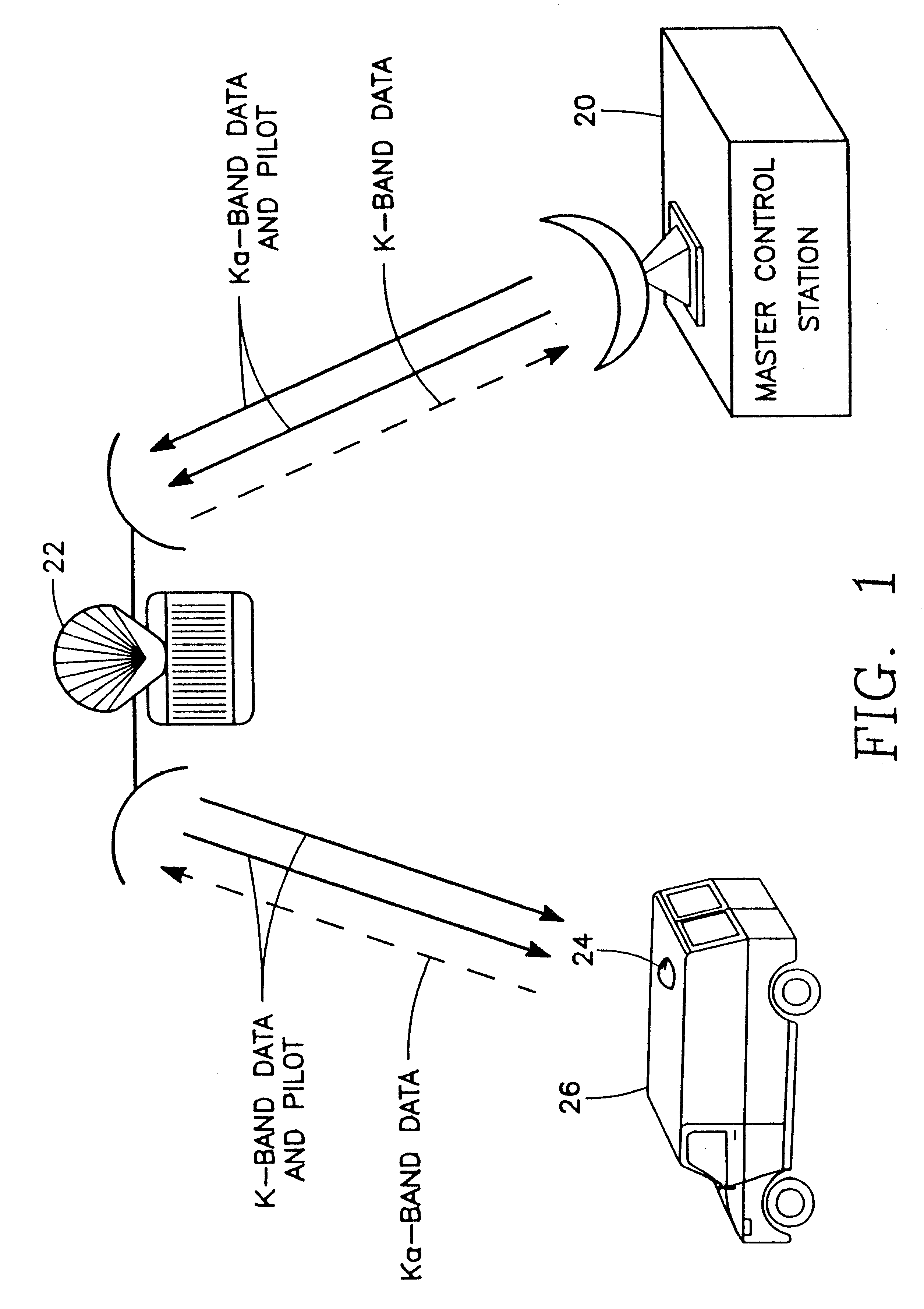
Referring to FIG. 1, a ground master control station 20 transmits Ka-band data to a geostationary satellite 22 and receives K-band data from the satellite 22. The satellite 22 converts the Ka-band data received from the ground station 20 to K-band data and transmits it to a compact satellite-tracking mobile vehicle antenna 24 of the present invention mounted on a ground vehicle 26. The Ka-band data transmitted by the master ground station 20 includes a pilot signal, so that the converted K-band data transmitted by the satellite 22 also includes a corresponding pilot signal received by the satellite-tracking mobile vehicle antenna 24. Furthermore, the mobile vehicle antenna 24 transmits Ka-band data to the satellite 22 which is converted to K-band data by the satellite 22 and transmitted to the master ground control station 20.

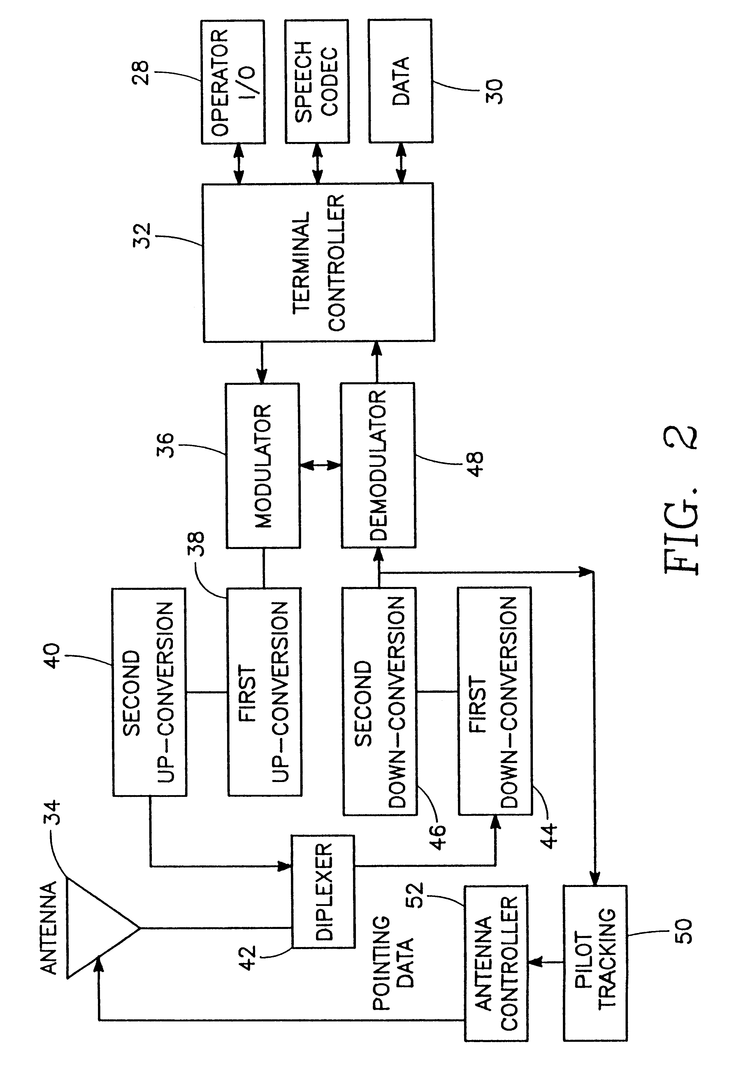
Referring to FIG. 2, the satellite-tracking mobile vehicle antenna 24 comprises a system including an operator input / output terminal 28, a data port 30, a term...


PUM


Abstract

A miniature dual-band two-way mobile satellite-tracking antenna system mounted on a movable vehicle includes a miniature parabolic reflector dish having an elliptical aperture with major and minor elliptical axes aligned horizontally and vertically, respectively, to maximize azimuthal directionality and minimize elevational directionality to an extent corresponding to expected pitch excursions of the movable ground vehicle. A feed-horn has a back end and an open front end facing the reflector dish and has vertical side walls opening out from the back end to the front end at a lesser horn angle and horizontal top and bottom walls opening out from the back end to the front end at a greater horn angle. An RF circuit couples two different signal bands between the feed-horn and the user. An antenna attitude controller maintains an antenna azimuth direction relative to the satellite by rotating it in azimuth in response to sensed yaw motions of the movable ground vehicle so as to compensate for the yaw motions to within a pointing error angle. The controller sinusoidally dithers the antenna through a small azimuth dither angle greater than the pointing error angle while sensing a signal from the satellite received at the reflector dish, and deduces the pointing angle error from dither-induced fluctuations in the received signal.

Description

BACKGROUND OF THE INVENTION1. Technical FieldThis invention is related to compact micro-wave satellite antennas and automatic antenna positioning systems for tracking a satellite from a moving vehicle.2. Background ArtAttitude control systems for mobile antennas in satellite communication systems are disclosed in U.S. Pat. Nos. 5,061,963, 4,873,526 and 4,725,843. In these devices, the antenna includes a feed horn facing a conical reflector dish. In order for the reflector dish to capture an adequate signal from the satellite, it must be rather large, typically on the order of a few hundred wave lengths across, resulting in the ungainly and large mobile antenna systems illustrated in the above-referenced patents. The relatively large reflector size provides an adequate antenna gain, arising from the directionality of the antenna gain pattern. The antenna must be pointed directly at the satellite in order to receive an adequate signal therefrom. Thus, such mobile antenna systems must ...

Claims


Application Information

Patent Timeline
Patent Type & Authority Patents(United States)
IPC IPC(8): H01Q19/10H01Q3/04H01Q19/13H01Q3/02H01Q1/32
CPCH01Q1/3275H01Q3/04H01Q19/132
Inventor DENSMORE, ARTHUR C.JAMNEJAD, VAHRAZWOO, KENNETH E.
Owner NASA
Why Eureka
Try Eureka