Ball valve with integrated removable flow venturi, flow balancing means, and pipe union means

Inactive Publication Date: 2002-04-02
SHERMAN JOHN C
View PDF10 Cites 53 Cited by
  • Summary
  • Abstract
  • Description
  • Claims
  • Application Information

AI Technical Summary

Benefits of technology

Each one of the functions described hereinabove is typically performed by a separate device in heating, ventilating, and air conditioning systems. Each one of the functions requires at least two piping connections, and every heat transfer coil installed to heat and cool a given space within a building requires all these devices to perform its function correctly. By combining all of these separate devices into a single

Problems solved by technology

Unfortunately, these component combinations can become very complex.
Multiply this by the fifty or so coils on a norm

Method used


Image

  • Ball valve with integrated removable flow venturi, flow balancing means, and pipe union means
  • Ball valve with integrated removable flow venturi, flow balancing means, and pipe union means
  • Ball valve with integrated removable flow venturi, flow balancing means, and pipe union means

Examples


Embodiment Construction

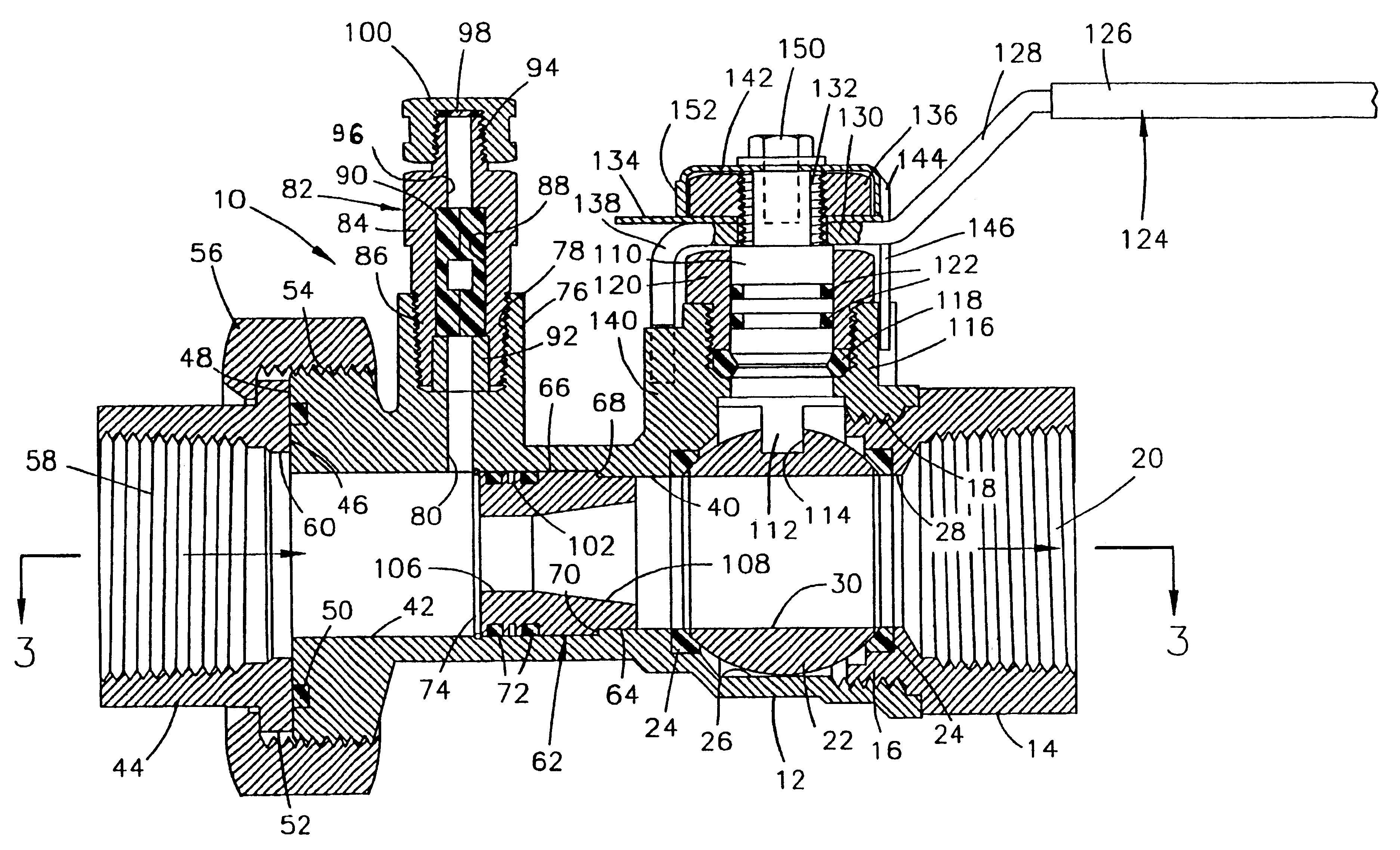
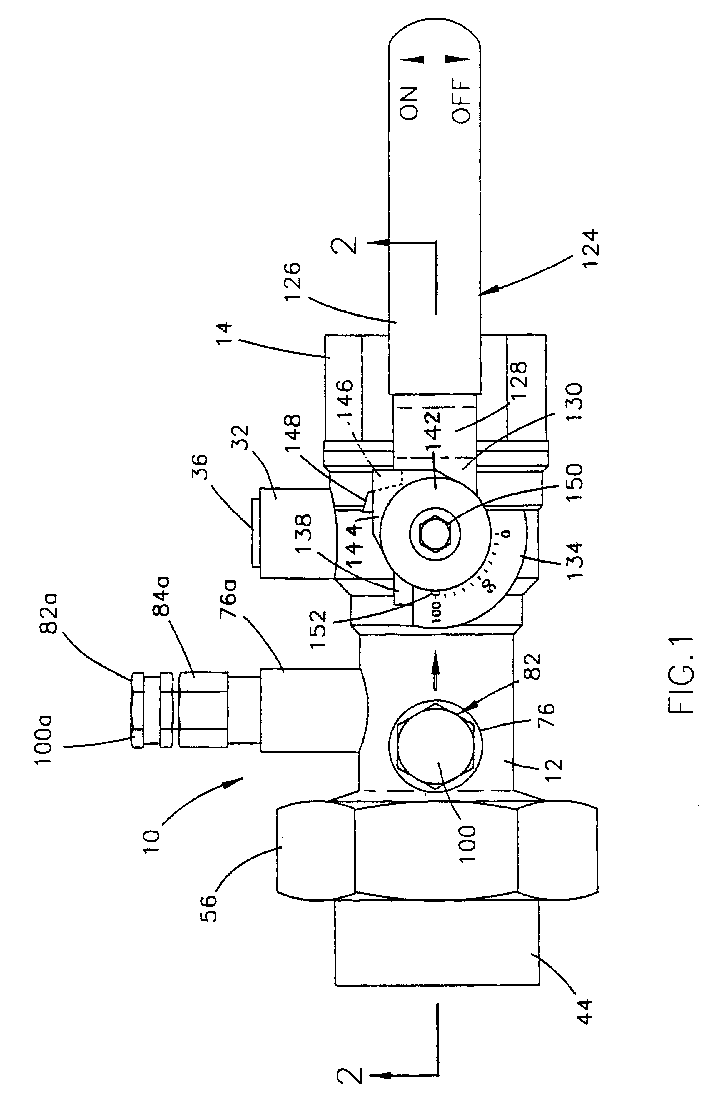
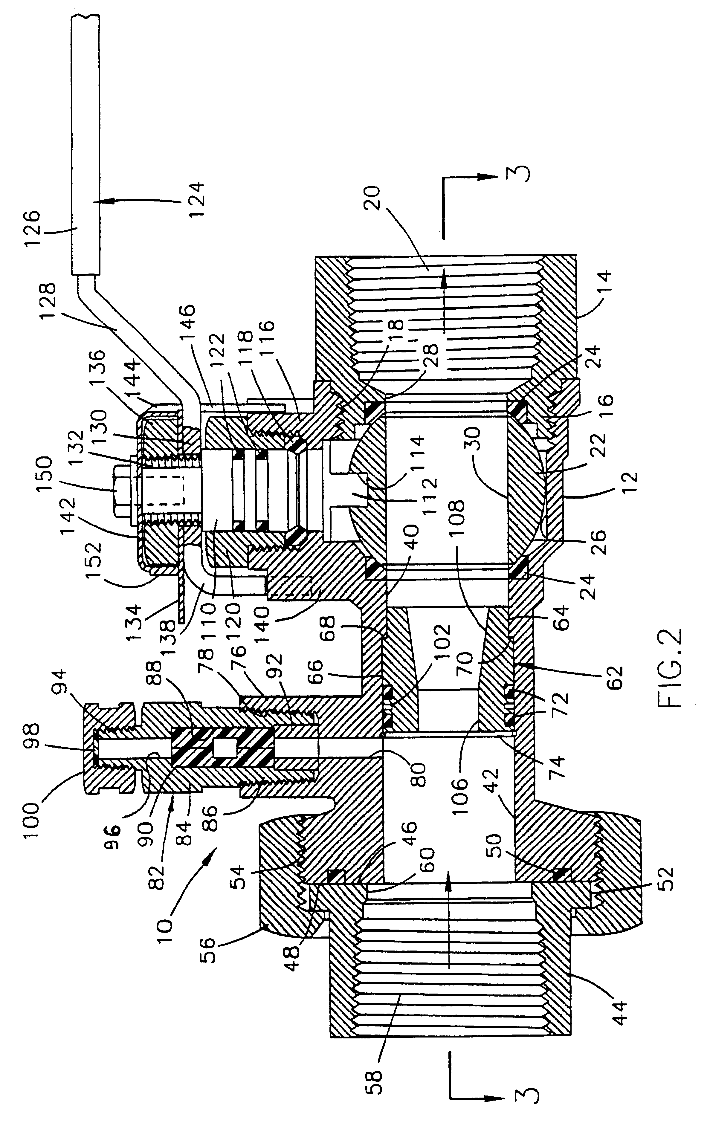
Referring now to the drawings, and in particular to FIGS. 1 and 2, the numeral 10 generally designates a ball valve assembly including a integrated removable venturi, a flow balancing means, and a pipe union means. The integrated ball valve assembly 10 comprises a valve body 12 that is provided on the exit end thereof with a valve body nut 14. The inner end of the valve body nut 14 is circular in shape and is provided with a peripheral threaded portion 16. The peripheral threaded inner end 16 of the valve body nut 14 is threadably mounted in the internally threaded valve body outlet end 18 of the valve body 12. The valve body nut 14 is provided with a threaded outlet port 20. A flow control quarter-turn ball valve 22 is rotatably mounted in a ball valve chamber 26 in the valve body 12 on a pair of ball seals 24. The flow control quarter-turn ball valve 22 is rotatably mounted about an axis perpendicular to the longitudinal axis of the valve body 12. The valve body nut 14 is provided...


PUM


Abstract

A valve assembly for use in heating, ventilating and air conditioning systems. The valve assembly includes a valve body having a chamber in which is rotatably mounted a quarter-turn flow control ball valve. A valve body nut having an outlet port is threadably mounted on the valve body adjacent the outlet end of the valve body chamber. A flow venturi is removably mounted in the inlet end of the valve body. A pipe union tailpiece is detachably mounted on the inlet end of the valve body. A pair of pressure/temperature readout ports are mounted on the valve body for use in determining the rate of fluid flow through the venturi. A vent plug is mounted on the valve body for venting air from the ball valve chamber.

Description

BACKGROUND OF THE INVENTION1. Field of the InventionThe field of art to which this invention pertains may be generally located in the class of devices relating to valves. Class 137, Fluid Handling, United States Patent Office Classification, appears to be the applicable general area of art to which the subject matter similar to this invention has been classified in the past.2. Description of the Prior ArtThis invention relates to a flow control ball valve with an integrated removable venturi, a flow balancing means, and a pipe union means for use in a heating, ventilating and air conditioning system. The integrated structure of the present invention combines the most sought after components used in piping fan coils and air handling units into a single compact, easy to install product. Heating and cooling systems have widely varying flow rates requiring different sized venturis to properly measure the flow through the systems. Whenever a heating, ventilating and air conditioning chil...

Claims


Application Information

Patent Timeline
IPC IPC(8): F16K27/06G01F1/34G01F1/44G01F15/00
CPCF16K27/067G01F1/44G01F15/005Y10T137/8309Y10T137/8326
Inventor SHERMAN, JOHN C.
Owner SHERMAN JOHN C
Why Eureka
Try Eureka