Pulse oximetry testing

a pulse oximeter and oximeter technology, applied in the field of pulse oximeter testing, can solve the problems of inability to fully test, inaccurate readings, abuse, etc., and achieve the effect of eliminating doubts about integrity and facilitating testing

Inactive Publication Date: 2003-01-28
CLINICAL DYNAMICS CORP
View PDF9 Cites 33 Cited by
  • Summary
  • Abstract
  • Description
  • Claims
  • Application Information

AI Technical Summary

Benefits of technology

Another object of the subject invention is to avoid the errors which may be introduced into the testing of a pulse oximeter when the oximeter is tested by clamping its probe onto a simulated finger containing optical elements, thus requiring precise positioning of the simulated finger in the probe.
Another object is to eliminate doubts about the integrity of testing a pulse oximeter which tests good although its probe cable may have a emerging discontinuity causing intermittent noise spikes which are filtered out by the oximetry circuitry but which could eventually degrade and cause inaccurate or no readings during critical use of the oximeter.
A still further object is to simplify the task of biomedical equipment technicians and other trained healthcare personnel in testing the basic operation of pulse oximeters used in hospitals and other patient-care facilities.

Problems solved by technology

Although test equipment has been developed for testing the accuracy of pulse oximeters, such equipment has been based on a particular testing philosophy which imposes certain undesirable limitations on the test results.
Such an approach, however, has not proved to be fully effective since the reliability of the testing can be compromised or indeterminate and desired testing flexibility is lacking, as hereinafter explained.
With an artificial finger, however, the photodiodes and the LEDs in the artificial finger must be placed exactly opposite the LEDs and photodiode, respectively, of the probe or else the light flashes will not be detected by the photodiodes.
Thus, if this placement is not exact, inaccurate readings will occur.
Thus, probe cables can easily fall on the floor by the bedside and be subjected to abuse.
Moreover, they are normally folded, wound, or otherwise compressed and stored in a drawer, sometimes rather haphazardly.
Because of the described construction, use and treatment of probe cables and their probes, they are very vulnerable to damage and defects.
Field studies with hospital biomedical technicians have shown that the majority of oximeter defects have been probe defects and that these defects are caused by frayed probe cable wires, that is, breaks or shorts, many of which occur intermittently.
If there is a defect in the probe cable, this testing approach may miss it or fail to isolate it.
For example, if the probe cable has frayed wires, front end circuitry in the oximeter may filter out the noise spikes caused by the fraying, and the display will indicate normal functioning, whereas in fact the probe cable is damaged and may later fail completely at a critical time.
Moreover, if the display on the tester indicates an erroneous reading, it may not be possible to determine if the problem is in the probe including the probe cable, or in the signal processing circuitry.
Furthermore, if the source of the problem is suspected to be in the probe, the tester provides no way of separately testing the probe cable and optics on the one hand, and the signal processing circuitry on the other hand, to isolate the problem area.
Thus, testing the oximeter as an integral entity, i.e., the probe and signal processing circuitry together, as the optical-interface approach requires, does not afford an unqualified independent assessment of these main parts, and especially of the parts most likely to fail.
In fact, this testing methodology may introduce other problems as explained above.

Method used


Image

  • Pulse oximetry testing
  • Pulse oximetry testing
  • Pulse oximetry testing

Examples


Embodiment Construction

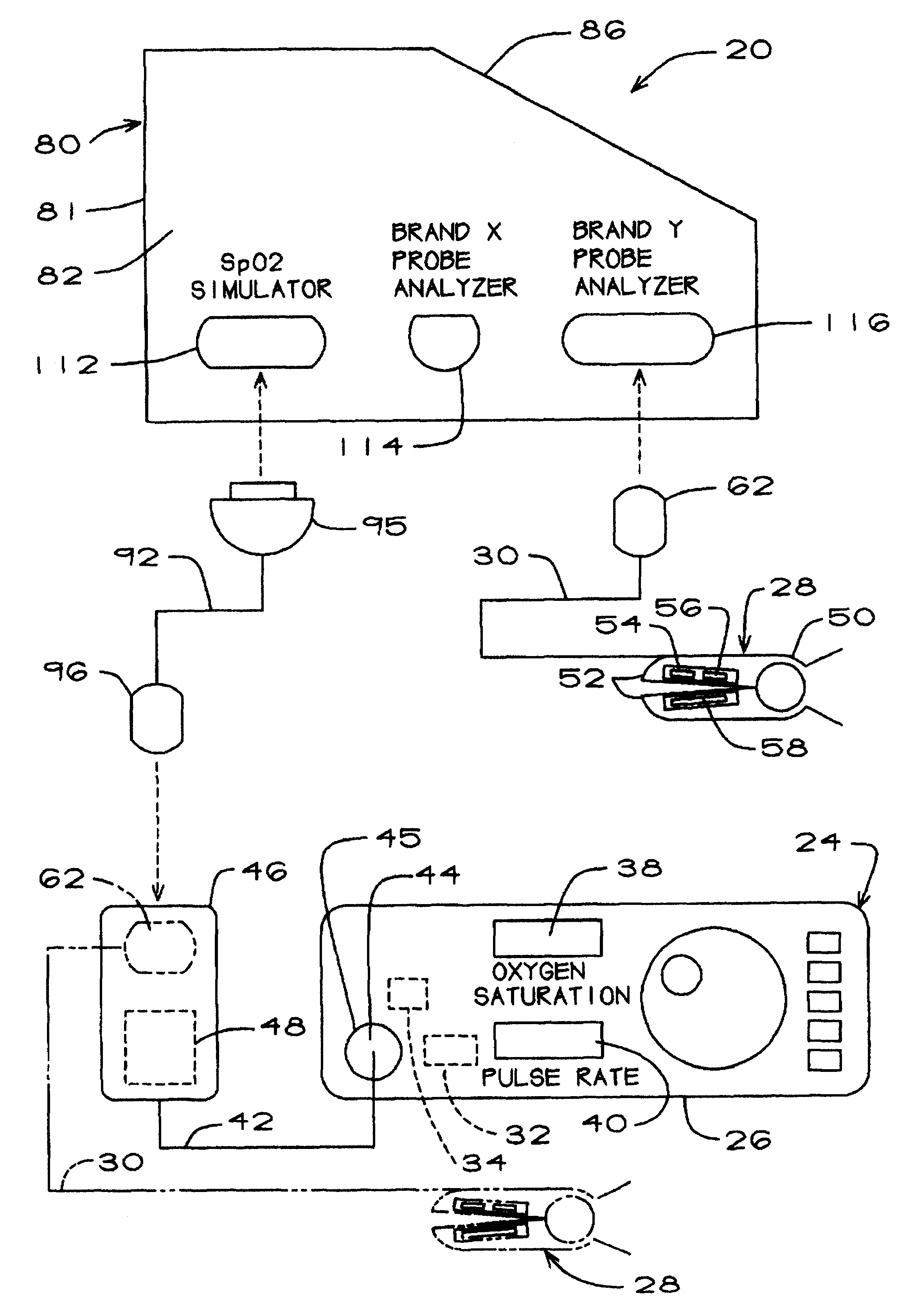
The pulse oximeter testing apparatus or analyzer of the present invention is generally represented by the numeral 20 in FIG. 1, which is a schematic drawing showing how the testing apparatus is connected to a pulse oximeter 24. Since reference will made herein to certain aspects of the pulse oximeter itself, it will be helpful at the outset to provide a brief general description of a typical pulse oximeter.

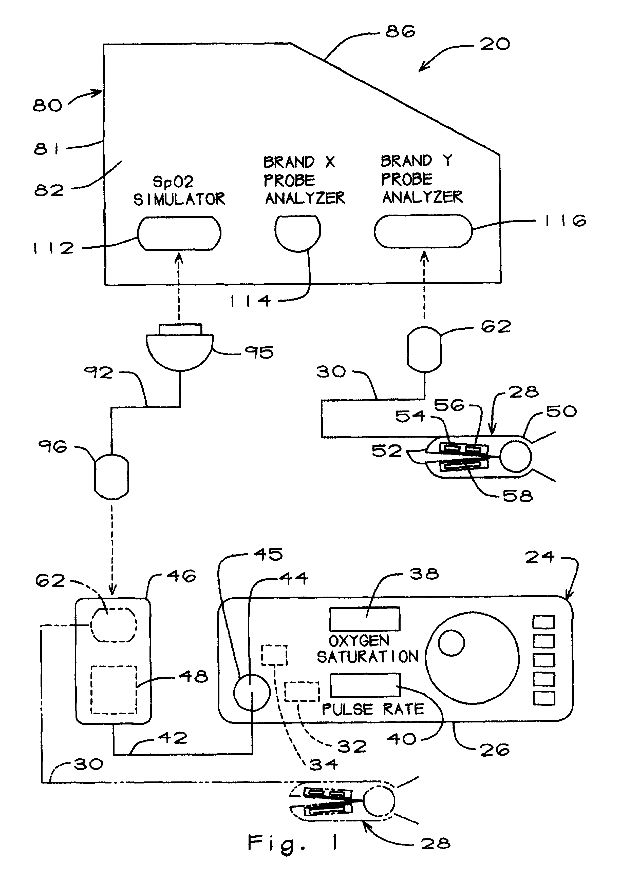
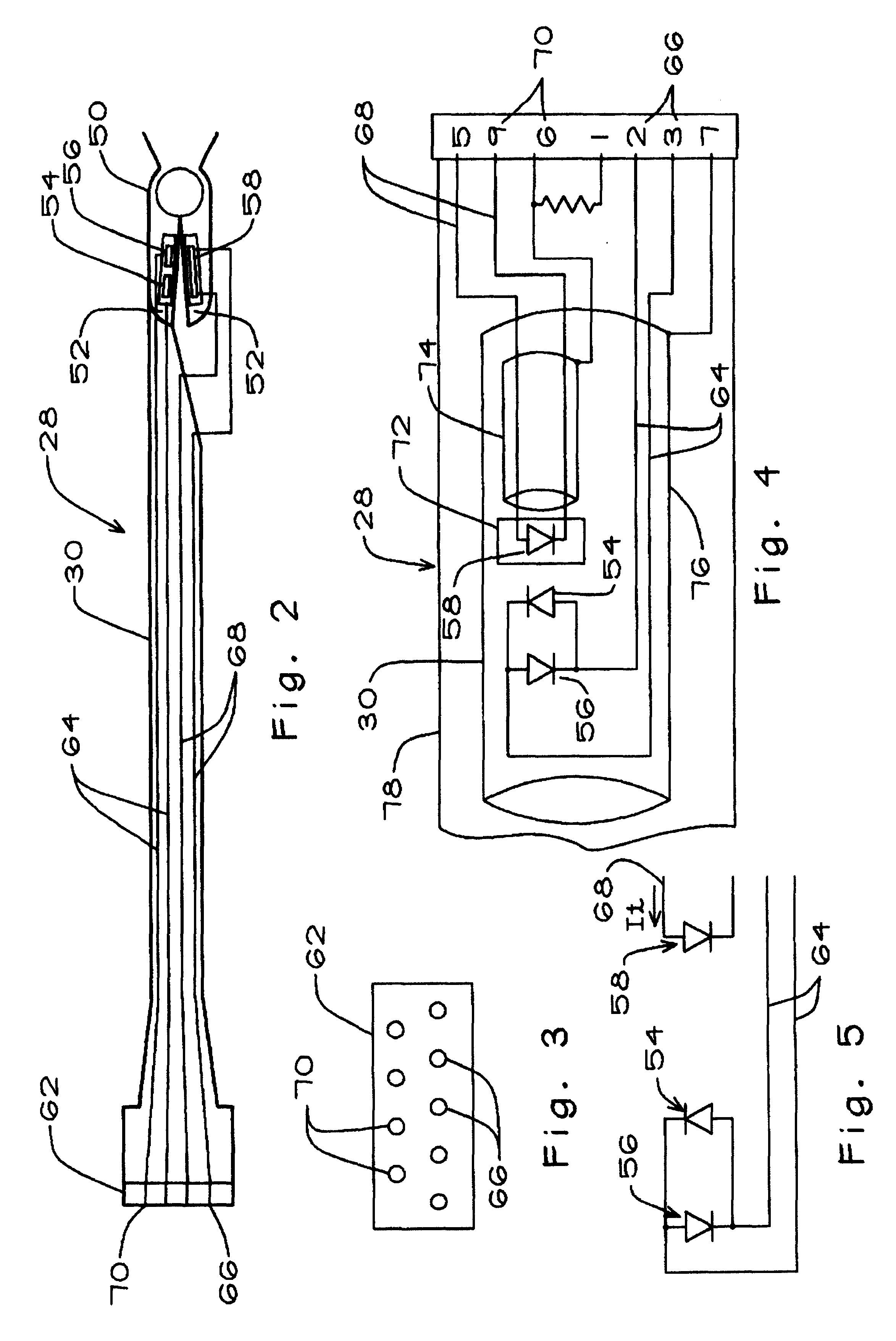
Thus, the pulse oximeter 24 (FIG. 1) includes a main unit 26 and a probe 28 which includes a probe cable 30. The main unit includes a signal processor 32, an LED driver 34, and upper and lower displays 38 and 40 for displaying the blood oxygen saturation SpO.sub.2 as a percentage and pulse rate in beats per minute. The main unit of the brand of oximeter shown and described herein also includes a preamp cable 42. The preamp cable terminates at one end in a proximal preamp connector 44 coupled to an interface connector 45 in the main unit 26 and at the opposite end in a distal. prea...


PUM

PropertyMeasurementUnit
timeaaaaaaaaaa
electrical continuityaaaaaaaaaa
electrical sensitivityaaaaaaaaaa

Abstract

A method and apparatus for testing a pulse oximeter which is based on the concept of an electrical interface between the testing instrument and the oximeter rather than an optical interface. The pulse oximeter signal processor is tested separately from the probe, and still further, the optical elements, that is, the LEDs and the photodiode, of the probe are tested separately from the probe cable. With the probe disconnected from the oximeter, a modulated electrical test signal representative of SpO2 values and other parameters is generated in response to an electrical signal from the oximeter, and the test signal is applied to the oximeter signal processor, whereby the display of the oximeter shows a value of SpO2 which is compared with the SpO2 value represented by the test signal. Independently, the probe including the probe cable, the LEDs and the photodiode are respectively and separately subjected to continuity and optical sensitivity tests. Each of the main components of the oximeter is thereby separately analyzed, and the source of a defect is isolated.

Description

FIELD OF THE INVENTIONThis invention pertains to pulse oximeter testing and more particularly to a method and apparatus for testing pulse oximeters.BACKGROUNDPulse oximeters are commonly used in hospitals and other patient-care facilities for monitoring the blood oxygen level of a patient in a non-invasive, continuous manner. The basis of operation of these instruments is the fact that blood absorbs red (R) and infrared (IR) light in different amounts depending on the level of oxygen in the blood (SpO.sub.2) and that a known relationship exists between the ratio of red to infrared light (R / IR) and blood oxygen level (SpO.sub.2).Thus, a pulse oximeter functions by detecting the amount of red and infrared light transmitted through a part of the body, usually a finger, to establish the R / IR ratio. It then compares this ratio with an internally stored database giving the relationship between R / IR ratios and SpO.sub.2 levels, determines the SpO.sub.2 level for the detected ratio, and dis...

Claims


Application Information

Patent Timeline
Patent Type & Authority Patents(United States)
IPC IPC(8): G01L25/00
CPCA61B5/14552A61B5/1495
Inventor COSTELLO, JR., LEO F.
Owner CLINICAL DYNAMICS CORP
Why Eureka
Try Eureka