Lens with external aperture stop

a technology of aperture stop and lens, applied in the field of compact lenses, can solve the problems of increasing the cost of assembling and mounting the lens in the lens cell, increasing the cost of the lens, and large number of elements tending to be relatively large, so as to improve the optical performance, high reliability, and high yield in volume manufacturing

Inactive Publication Date: 2005-09-20
NING ALEX
View PDF20 Cites 26 Cited by
  • Summary
  • Abstract
  • Description
  • Claims
  • Application Information

AI Technical Summary

Benefits of technology

[0014]The above-noted problems, and others, are overcome in accordance with this invention by a lens for portable digital devices, in particular digital cameras, which has an aperture stop in front of the lens, external to the lens, where a combined variable aperture and shutter can be easily positioned with precision.
[0016]The aperture / shutter device is external to the optical elements, so the optical elements can be assembled into a precision lens barrel independent of the aperture / shutter device. The performance of such a lens can be tested and verified before integration with an aperture / shutter device. Integration of such pre-assembled lenses with the aperture / shutter device can be performed with high reliability and repeatability, resulting in high yields in volume manufacturing.
[0017]It is, therefore, an object of this invention to provide a compact lens assembly particularly suitable for use with portable digital devices, such as digital cameras.
[0018]Another object is to provide a compact lens assembly having an aperture stop external to the lens assembly where a combined variable aperture and shutter device can be positioned.
[0019]A further object is to provide an asymmetric lens assembly with improved optical performance and having all glass lens elements with spherical surfaces.

Problems solved by technology

These lenses that require a large number of elements tend to be relatively large, heavy and expensive to manufacture.
The cost of these lenses increases with the number of elements and the resulting increased costs in assembling and mounting them in a lens cell.
Where all elements have spherical surfaces, generally a high number of lens elements is required, making the lens long and heavy and expensive to produce.
Aspheric lenses have some optical advantages, but cannot be easily produced by traditional grinding and polishing techniques.
While molded plastic elements are inexpensive to produce, the level of precision of the lenses is not sufficient for high-resolution cameras.
While it is possible to make glass aspheric lens elements, manufacturing to the required accuracy is difficult and expensive when compared to manufacture of spherical lens elements.
It is generally believed that achieving good aberration correction without this symmetrical arrangement of lens elements would be difficult.
However, it is difficult and expensive to integrate a variable aperture / shutter device with this type of optical design since it is difficult to keep the lens elements precisely with the aperture device located between the elements.
However, that deign has a maximum relative aperture of f / 4, too slow for use with cameras to be used at relatively low light levels.
That design further requires seven elements, making it excessively long, heavy and expensive to products for use in compact cameras, especially in compact digital cameras.

Method used


Image

  • Lens with external aperture stop
  • Lens with external aperture stop

Examples


Embodiment Construction

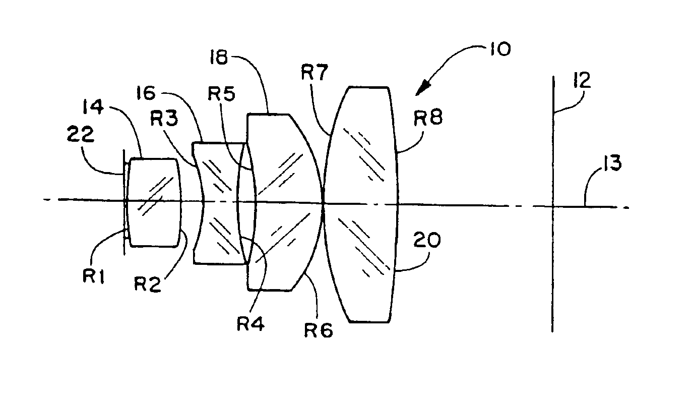
[0024]Referring to FIG. 1, there is seen a schematic axial section view of a lens assembly 10 for forming an image at a image plane 12, which in a digital cameral is the sensor plane and in a film type camera is the film plane. The front or distal end of the lens is to the left in FIG. 1. Line 13 represents the lens optical axis.

[0025]The lens assembly 10 includes a bi-cover distal lens element 14 and a proximal lens group including a first bi-concave element 16, a second meniscus element 18 and a third bi-convex element 20. The aperture stop plane is schematically indicated by line 22, closely adjacent to distal lens element 14. Distal element 14 provides most of the focussing power while the proximal group of elements 16, 18 and 20 provides aberration compensation to correct for any optical imperfections present in element 14. Any suitable spacing between lens elements may be used. Aperture stop 22 is preferably as close to distal element 14 as is practical. Overall length from ap...


PUM


Abstract

A lens assembly particularly suited to use with high resolution digital cameras and other portable electronic devices. The lens includes a positive powered front group having one or two elements and a second, aberration correcting, rear group having in order from the front a bi-concave element, a meniscus element and a bi-concave element. The aperture stop plane is just in front of the front group. A combined operator and shutter device is positioned at the aperture stop plane. All of the lens elements are made of glass and have spherical surfaces.An objective lens for use in a digital camera or cell phone having a camera body, the lens having a sensor such as a CCD providing an active surface that serves as a focal plane, a digital image corresponding to a varying light image falling on the focal plane, a lens assembly for forming the varying light image, the lens assembly comprising a positive doublet having a first and a second element or a singlet, at the object end of the lens assembly followed by a lens element group spaced from the positive doublet or alternatively, a positive singlet and having three elements, in order from the object end, a bi-concave element, a meniscus element and a bi-convex element, and an aperture stop located at a predetermined distance in front of the positive doublet or positive singlet lens element at the object end of the lens assembly.<?insert-end id="INS-S-00001" ?>

Description

[0001]This application is a continuation in part of copending U.S. patent application Ser. No. 09 / 390,992, filed Sep. 7, 1999, now abandoned.FIELD OF THE INVENTION[0002]This invention relates to compact lenses for camera applications; in particular, for digital cameras.BACKGROUND OF THE INVENTION[0003]Digital cameras utilizing high-resolution electronic imaging sensors (so-called “megapixel” cameras) require high resolution optics. For the consumer market, it is important that the lenses can be produced in high volume inexpensively. With many sensors, a mechanical shutter and / or a variable aperture are necessary or desirable to optimize the imaging performance of the sensor.[0004]A variable aperture is generally desirable to enable the camera to take acceptable pictures in a wide range of lighting conditions. Where the environment is darker, the aperture must be fully open to allow sufficient light to illuminate the sensor at an optimum level. In a brighter environment the aperture ...

Claims


Application Information

Patent Timeline
Patent Type & Authority Patents(United States)
IPC IPC(8): G02B9/06G02B9/00G02B9/34G02B13/00G02B13/04
CPCG02B9/34G02B13/005
Inventor NING, ALEX
Owner NING ALEX
Why Eureka
Try Eureka