Interlocking segmented coil array

a coil array and segmented coil technology, applied in the direction of magnetic circuit rotating parts, magnetic circuit shape/form/construction, magnetic bodies, etc., can solve the problems of reducing the efficiency of motors and reducing the magnetic flux density, so as to maximize the total length of working conductors, minimize the thickness of coils and magnet flux gaps, and provide electromotive interaction.

Inactive Publication Date: 2006-01-24
KINETIC ART & TECH CORP
View PDF38 Cites 15 Cited by
  • Summary
  • Abstract
  • Description
  • Claims
  • Application Information

AI Technical Summary

Benefits of technology

[0003]In view of the well known disadvantages in the above-mentioned prior art, it is an object of the present invention to provide a novel coil structure which more efficiently provides electromotive interaction between these new coils and the magnets within a rotary motor or generator of the type having a generally flat, ring-shaped coil structure and employing an axial gap magnet structure, such as in disc or pancake motors, while minimizing the thickness of the coil and magnet flux gap. Specifically, the invention relates to the construction and shape of the individual coils making up a coil array (circular or arc-shaped arrangement of coils) so as to allow interlocking or overlapping of multiple coils to form a thin disc coil array having double the density of, but not significantly more thickness than, non-overlapping coil arrays. The radially extending conductor portions of each coil all lie in a first plane while the circumferentially extending portions of each coil's conductors lie above and below said first plane.
[0004]Another object of the present invention is to maximize the total length of the working conductors within a circular coil array by overlapping three adjacent coils, so as to maximize the electromotive interaction for a motor or generator of a given diameter. For any given device diameter, conductor cross-sectional area, and magnetic flux density, this technique maximizes the torque which may be produced by a motor, or the voltage produced by a generator.
[0005]Another object of the invention is to provide a mechanism whereby multiple coil arrays may be closely stacked with corresponding magnetic rotors in alternating layers so as to increase the total coil area within a motor or generator of a given diameter. This increased coil area allows increased interaction between coils and magnets, improving the power conversion with the motor or generator.

Problems solved by technology

While this arrangement allows closer packing of the working conductors, it also requires that the gap between the rotor's magnets and flux return be about twice as thick as would be required for a single thickness of a non-overlapping coil, thus reducing the magnetic flux density and thus reducing the motor's efficiency.

Method used


Image

  • Interlocking segmented coil array
  • Interlocking segmented coil array
  • Interlocking segmented coil array

Examples


Embodiment Construction

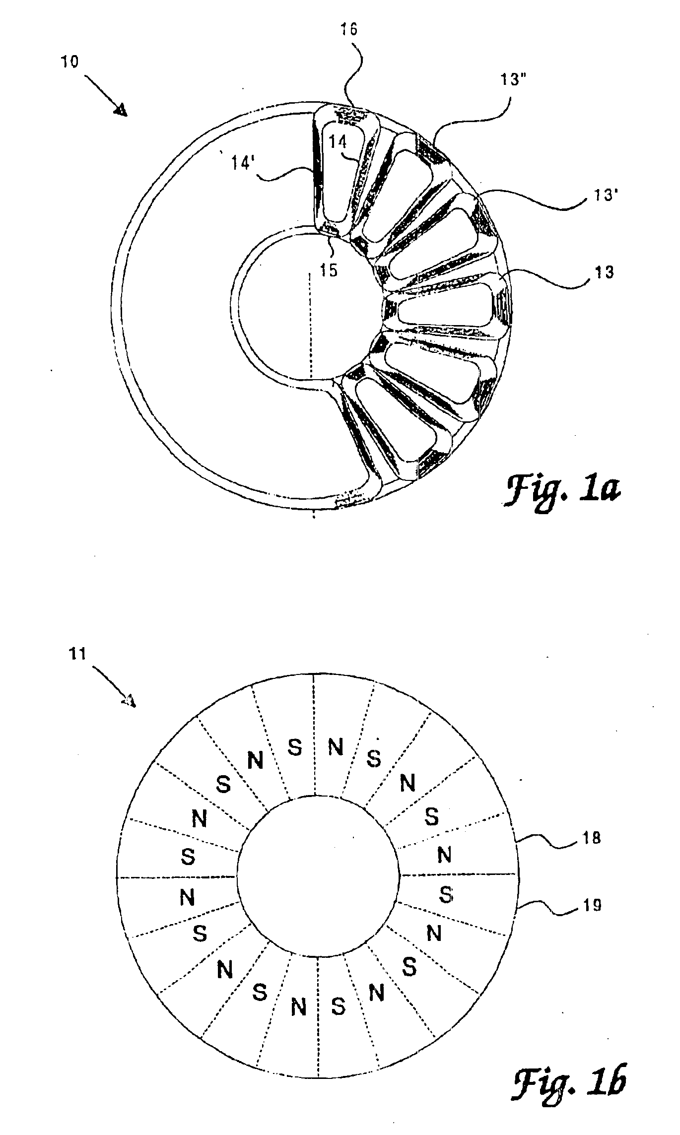
[0018]Referring now to the drawings and particularly to FIG. 1, there is shown a prior art planer coil assembly 10 and a magnet rotor 11 which may be used to make a typical prior art disc-type motor. This coil assembly 10 consists of several individual coils 13, 13′, 13″ arranged in a circular pattern, each coil 13 having two radially extending conductor portions or legs 14, 14′, an inner circumferentially extending leg 15 and an outer circumferentially extending leg 16, all lying in a single plane. In a motor utilizing such a coil assembly, the magnet rotor 11, having alternating North / South poles 18, 19 arranged in a corresponding circular pattern and affixed to a central shaft (not shown), rotates in a plane closely adjacent to, but spaced slightly above and / or below, the plane containing the coils 13, 13′, 13″. While two magnet rotors 11 may be used, one on either side of the coil assembly 10, only one may be used if a magnetic flux return, such as a soft iron disc (not shown), ...


PUM

PropertyMeasurementUnit
angleaaaaaaaaaa
sizeaaaaaaaaaa
densityaaaaaaaaaa

Abstract

Disclosed is a Segmented Coil Array (“SCA”) for use in rotary electromotive devices, such as motors and generators, which employ multiple coils operating within an axial gap magnetic structure. Individual conductor coils have offset circumferentially extending portions so as to allow interlocking of adjacent coils radially extending portions to form a circular array in which all of the coils' working conductors, which are those in the axial magnetic field, can be oriented in the same plane. This construction allows minimum magnet gap spacing, thus, maximizing the available magnetic flux. The resulting SCA may easily be commuted as a three-phase motor, actuator, or generator. The invention also provides a structure whereby multiple coil arrays and associated magnetic rotors may be alternately stacked in layers so as to further increase the total coil working area within a motor or generator of a given diameter.

Description

FIELD OF THE INVENTION[0001]This present invention relates generally to electrical generator or motor structures and more specifically to brushless electromotive devices of the type which employ a flat coil array or structure operating within an axially-oriented magnetic field having flux lines mostly perpendicular to the working conductor portion of the coils. This may include disc or pancake rotary motors as well as linear motors having such flat coils and magnetic structure.BACKGROUND OF THE INVENTION[0002]Motors employing disc-shaped coil armatures and brush commutation have been in use since the late 1950's. Brushless disc-type motors were later developed, employing rotating magnets, coil stators and electronic commutation. Such motors have been used in large numbers in audio and video tape recorders and computer disc drives. In such a motor, a magnetic rotor disc with alternating North / South pole pieces rotates above and / or below a plane containing several flat, stator coils l...

Claims


Application Information

Patent Timeline
Patent Type & Authority Patents(United States)
IPC IPC(8): H02K1/22H02K3/04H02K3/00H02K3/12H02K3/47H02K16/00H02K16/02H02K21/24
CPCH02K3/04H02K3/47Y10T29/49071Y10T29/49009H02K21/24H02K1/22H02K3/00H02K16/00
Inventor KESSINGER, JR., ROY LEESTAHURA, PAUL ANTHONYRECEVEUR, PAUL ERICDOCKSTADER, KARL DAVID
Owner KINETIC ART & TECH CORP
Why Eureka
Try Eureka