Method for determining motion compensation

a motion compensation and motion compensation technology, applied in the field of motion compensation, can solve the problems of deteriorating precision of the level of prediction, inability to accurately make predictions, and inability to make predictions at a higher level of precision, so as to achieve high pixel density, and ensure high level of precision

Inactive Publication Date: 2006-09-12
PANASONIC CORP
View PDF34 Cites 0 Cited by
  • Summary
  • Abstract
  • Description
  • Claims
  • Application Information

AI Technical Summary

Benefits of technology

[0014]Therefore, according to the present invention, a time position of a reference image is compensated by using a certain motion vector depending on the need so that a plurality of pieces of reference images sampled at different times according to the motion of a block unit, including at least one pixel, which is detected at a certain time interval, become images of the input image at the above time intervals from the position of the input image. Thus, it is possible to obtain a plurality of pieces of images at positions of the above-described time intervals from the position of the input image. By combining these images together, it is possible to obtain a reference image of high pixel density. Based on this reference image of high pixel density, a pixel value at a position compensated by the detected motion portion is calculated and this is used as a determined value. Accordingly, it is possible to determine motion compensation at a very high level of precision.
[0015]Further, according to the present invention, a vector for carrying out compensation of a time position of the reference image can be calculated from motion of the image detected at a certain time interval, so that it is not necessary to detect again the motion vector for correcting the time, and motion compensation at a high level of precision can be ensured.
[0016]Further, by using an interlace signal as an input signal and using two fields in a certain frame for a reference image, it becomes possible to suitably apply the above method for determining motion compensation to a frame image, thus ensuring a determination at a high precision level of motion compensation based on a frame.
[0017]Further, since the same value is used for a block of each input image, of which whole or part of spatial position of each block is superposed, among blocks of a plurality of pieces of input images, as motion detected at a certain time interval in a block unit including at least one pixel, it is not necessary to carry out motion detection a plurality of times for many blocks of the plurality of input images, thus ensuring a determination of motion compensation at a high level of precision.

Problems solved by technology

The above-described conventional method for determining motion compensation, however, has problems that it is not possible to accurately determine motion compensation and that, even if it is possible to correctly determination of motion compensation, the image density of an image to be referred to becomes the image density of a reference image, which makes it impossible to make prediction at a higher level of precision.
In a vector in which this phenomenon occurs, there is a problem that the precision of the level of prediction is deteriorated.
However, in this case, motion compensation is determined from one piece of reference image and the pixel density of an image to be referred to becomes the pixel density of the reference image, so that there is a limit to carrying out a determination of motion compensation at a higher level of precision. FIG. 8 shows a case of determined move compensation by generating a block from a field for an input of an interlace signal.
Thus, there is a limit to carrying out a determination of motion compensation at a high level of precision when motion compensation is carried out based on a field.
This problem also arises when motion compensation is carried out by using a non-interlace signal as an input.
In both cases, the pixel density of the image to be referred to becomes the pixel density of the reference image, and there is a limit to carrying out a determination of motion compensation at a higher level of precision.

Method used


Image

  • Method for determining motion compensation
  • Method for determining motion compensation
  • Method for determining motion compensation

Examples


first embodiment

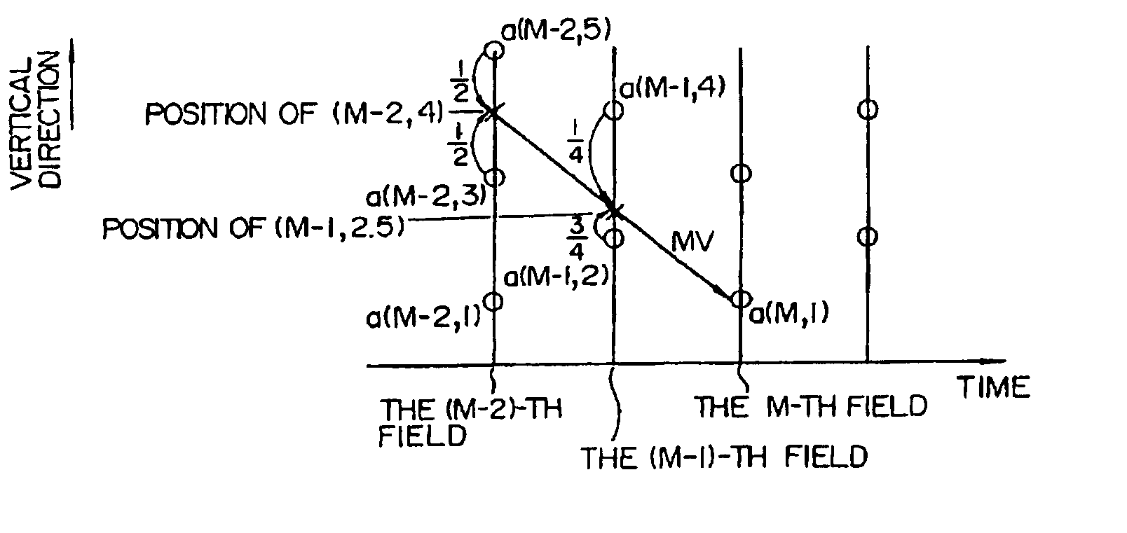
[0026]FIG. 1 is a diagram for explaining the present invention. FIG. 1 assumes the determination of motion compensation based on an interlace signal as an input signal so that a block is generated from an image within a field and a field image is used as a base. In this case, the input image is in the M-th field and a reference image is in both the (M−1)-th field and the (M−2)-th field. Now, assume that a motion vector (MV) for predicting move compensation of a certain block is to be detected in a two-field instance, that is, between the M-th field and the (M−2)-th field. To simplify the explanation, of the detected moves, only motion in the vertical direction will be considered, and a pixel value is expressed as a(x, y). In this case, x represents a field number and y represents a line number. Line numbers are placed in the order of 1, 2, . . . , starting from the bottom in a line interval of the frame. A position of each pixel in a vertical direction is expressed always in the uni...

fourth embodiment

[0042]FIG. 5 is a diagram for explaining the present invention. The fourth embodiment takes the same assumptions as those of the first embodiment, and an interlace signal is used as an input signal, an input image is in the M-th field and a reference image is in both the (M−1)-th field and the (M−2)-th field. Assume in FIG. 5 that a motion vector (MV) for determining motion compensation of a certain block is to be detected in a two-field interval, that is, between the M-th field and the (M−2)-th field. To simplify the explanation, of the detected motion, only motion in a vertical direction will be considered, and a pixel value at each pixel position is expressed in the same manner as that of FIG. 1.

[0043]Now consider the case of obtaining a determined value of a(M, 1). When it is assumed that the vertical component of the detected MV is 3, the determined value of move compensation of the a(M, 1) becomes the pixel value at the position of (M−2, 4). First, this pixel value is obtained...


PUM


Abstract

A method for predicting motion compensation for determining of an input image based on a motion vector of the input image from this input image to a reference image which has been sampled at a first set time, and the method includes calculating a motion vector of the input image based on a move, at a second set time, of a block unit which is a part of the input image and consists of a plurality of pixels, and calculating a motion vector of the reference image based on a move, at the first set time, of a block unit which is a part of the reference image and consists of a plurality of pixels. Move compensation of the input image is calculated both from the motion vector of the input image and from the motion vector of the reference image, to thereby realize a method for determining motion compensation with high precision.

Description

[0001]This is a reissue of U.S. Pat. No. 5,745,182 which is a division of application Ser. No. 07 / 970,046 filed Nov. 2, 1992, now U.S. Pat. No. 5,369,449. <?insert-start id="INS-S-00002" date="20060912" ?>This application has the following co-pending related reissue applications: Ser. No. 09 / 833,680 filed Apr. 13, 2001, Ser. No. 09 / 833,769 filed Apr. 13, 2001, Ser. No. 09 / 833,770 filed Apr. 13, 2001, Ser. No. 09 / 866,811 filed May 30, 2001 and Ser. No. 10 / 895,283 filed Jul. 21, 2004.<?insert-end id="INS-S-00002" ?>BACKGROUND OF THE INVENTION[0002]1. Field of the Invention[0003]The present invention relates to a method for determining motion compensation of a moving image to be utilized in an apparatus which requires a prediction of a moving image such as an image transmission apparatus and an image apparatus.[0004]2. Description of the Prior Art[0005]With the progress of semiconductor technologies, methods for determining motion compensation to be utilized for a transmis...

Claims


Application Information

Patent Timeline
Patent Type & Authority Patents(United States)
IPC IPC(8): H04N7/32G06T9/00H04N5/14H04N7/26H04N7/36H04N7/46
CPCH04N5/145H04N19/105H04N19/51H04N19/577H04N19/137H04N19/523H04N19/112
Inventor YUKITAKE, TAKESHIINOUE, SHUJI
Owner PANASONIC CORP
Why Eureka
Try Eureka