Connecting device for connecting a fan blade to a rotor of a motor of a ceiling fan

a technology of connecting device and ceiling fan, which is applied in the direction of wind motor components, non-positive displacement fluid engines, liquid fuel engine components, etc., can solve the problems of inconvenient assembly of the mounting arm b>21/b> on the rotor, inconvenient assembly of the fan blade, and inconvenient assembly of the mounting arm b>21/b>, etc., to achieve substantial reduction in packaging and transportation costs and easy fabrication

Inactive Publication Date: 2006-12-26
CHIEN LUEN INDS
View PDF34 Cites 9 Cited by
  • Summary
  • Abstract
  • Description
  • Claims
  • Application Information

AI Technical Summary

Benefits of technology

[0007]The object of the present invention is to provide a connecting device which is easy to fabricate and which can permit substantial reductions in the packaging and transport costs thereof.

Problems solved by technology

It is inconvenient to assemble the fan blades 13 due to the use of the screw fasteners 14, 15.
However, the assembly of the mounting arm 21 on the rotor (not shown) is still inconvenient to conduct.
In addition the mounting arm 21 involves increased packaging and transport costs.

Method used


Image

  • Connecting device for connecting a fan blade to a rotor of a motor of a ceiling fan
  • Connecting device for connecting a fan blade to a rotor of a motor of a ceiling fan
  • Connecting device for connecting a fan blade to a rotor of a motor of a ceiling fan

Examples


Embodiment Construction

[0019]Before the present invention is described in greater detail, it should be noted that same reference numerals have been used to denote like elements throughout the specifications.

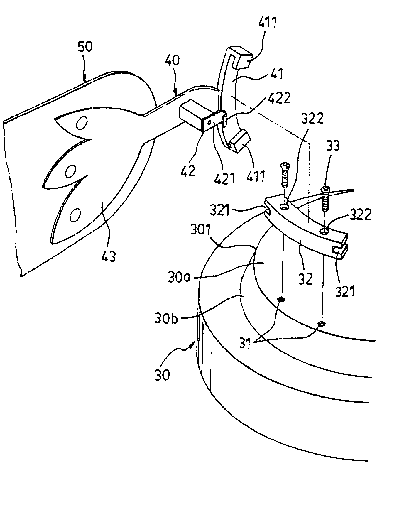
[0020]Referring to FIGS. 4 and 5, a first preferred embodiment of a connecting device according to the present invention is shown to be adapted to connect a fan blade 50 to a rotor 301 of a motor 30. The rotor 301 has a bottom member 30a which is disposed transverse to the axial direction, and which has two screw holes 31 formed therein adjacent to a periphery thereof. A circumferential wall extends upwardly from the perpher of the bottom member 30a and diverges upwardly so as to form an annular slanting wall 30b. An elongate mounting block 32 is mounted on the bottom member 30a, and has two through holes 322 such that two screw fasteners 33 respectively pass through the through holes 322 to engage threadedly the screw holes 31 so as to secure the mounting block 32 on the bottom member 30a. Two elongat...


PUM


Abstract

A connecting device includes a bottom member with a periphery for attaching on a rotor of a motor, a circumferential wall which extends upwardly from the periphery, and a mounting arm which has an anchored end adapted for mounting the fan blade thereon and an anchoring end for anchoring on the bottom member such that the mounting arm is oriented in a radial direction relative to the bottom member by guidance of a guiding member. A tightening member is disposed to tighten the anchoring end relative to the bottom member through a clamping force generated in a circumferential direction of the bottom member when the anchoring end is pulled away from the bottom member in the radial direction. A retaining member is disposed between the tightening member and the anchored end in the radial direction, and has an engaging spring member that abuts against the circumferential wall once the anchoring end is moved away from the bottom member.

Description

BACKGROUND OF THE INVENTION[0001]1. Field of the Invention[0002]This invention relates to a connecting device for a ceiling fan, more particularly to a connecting device for connecting a fan blade to a rotor of a motor of a ceiling fan.[0003]2. Description of the Related Art[0004]Referring to FIG. 1, a conventional ceiling fan 10 is shown to comprise a motor casing 16 for housing a motor 12 which includes a stator 122 and a rotor 121 that is concentrically surrounded by the stator 122 and that is rotatable about an axial direction. A plurality of fan blades 13 are connected to the rotor 121 by mounting arms, 11 respectively. Each mounting arm 11 has two plate-like connecting ends 111,113 which are mounted respectively and securely on the rotor 121 and the corresponding fan blade 13 by means of screw fasteners 14,15. It is inconvenient to assemble the fan blades 13 due to the use of the screw fasteners 14, 15.[0005]To facilitate assembly of the ceiling fan, referring to FIGS. 2 and 3...

Claims


Application Information

Patent Timeline
Patent Type & Authority Patents(United States)
IPC IPC(8): B25G3/00F04D25/08F04D29/34
CPCF04D25/088F04D29/34Y10T403/606F05D2260/38F05D2260/36F16B2200/69
Inventor WU, SAN-CHI
Owner CHIEN LUEN INDS
Why Eureka
Try Eureka