Indexable insert and cutting tool having indexable insert

a cutting tool and indexable technology, applied in the direction of turning machine accessories, manufacturing tools, shaping cutters, etc., can solve the problems of poor cutting chip discharge properties, high cost, and time-consuming for cutting type chips to be replaced, so as to prevent vibration and facilitate the attachment to the holder

Inactive Publication Date: 2010-04-27
POLY TEC PROD
View PDF24 Cites 6 Cited by
  • Summary
  • Abstract
  • Description
  • Claims
  • Application Information

AI Technical Summary

Benefits of technology

[0012]A primary object of the present invention is to provide an indexable insert having good clamping properties. Another object of the present invention is to provide a cutting tool for reliably clamping the indexable insert not to generate chatter vibration. Still another object of the present invention is to provide a cutting tool with high index accuracy at the position of a cutting edge. A further object of the present invention is to provide a high-performance indexable insert being superior in cutting chip discharge properties and capable of performing undercut processing and an inner diameter cutting processing.
[0018]When the cutting edge has brought into a concavely curved shape, as described in claim 4, cutting chips are curled, so that the cutting chips are easily removed.
[0020]The base of the indexable insert fitted in an insert pocket of the holder is not concealed as in a case where a sleeve is used but is exposed from the holder. That is, a top surface of the indexable insert fixed to the holder is exposed from the holder. Therefore, the indexable insert is easily attached to the holder. Moreover, the indexable insert can be firmly fixed to the holder using a bolt, a clamp, or the like. Accordingly, it is possible to prevent chatter vibration from being generated in the indexable insert.
[0021]The side relief face of the indexable insert connects with one side surface of the holder so as to be flush therewith, so that the holder does not prevent the cutting chips from being removed.

Problems solved by technology

The brazing type requires a lot of time to replace the chip 32 when the chip's edge is damaged, which is not economical.
The throwaway type is generally used for processing a large-diameter hole in a large-sized component such as an automobile component, however, this type is not used for processing a very small-diameter hole in a small-sized component such as a component for OA equipment or an electronic component.
Therefore, the front end surface of the sleeve 46 is positioned so as to close a hole of a work piece at the time of inner diameter cutting processing, resulting in poor cutting chip discharge properties.
Further, when the sleeve 46 is used, undercut processing cannot be performed.

Method used


Image

  • Indexable insert and cutting tool having indexable insert
  • Indexable insert and cutting tool having indexable insert
  • Indexable insert and cutting tool having indexable insert

Examples


Embodiment Construction

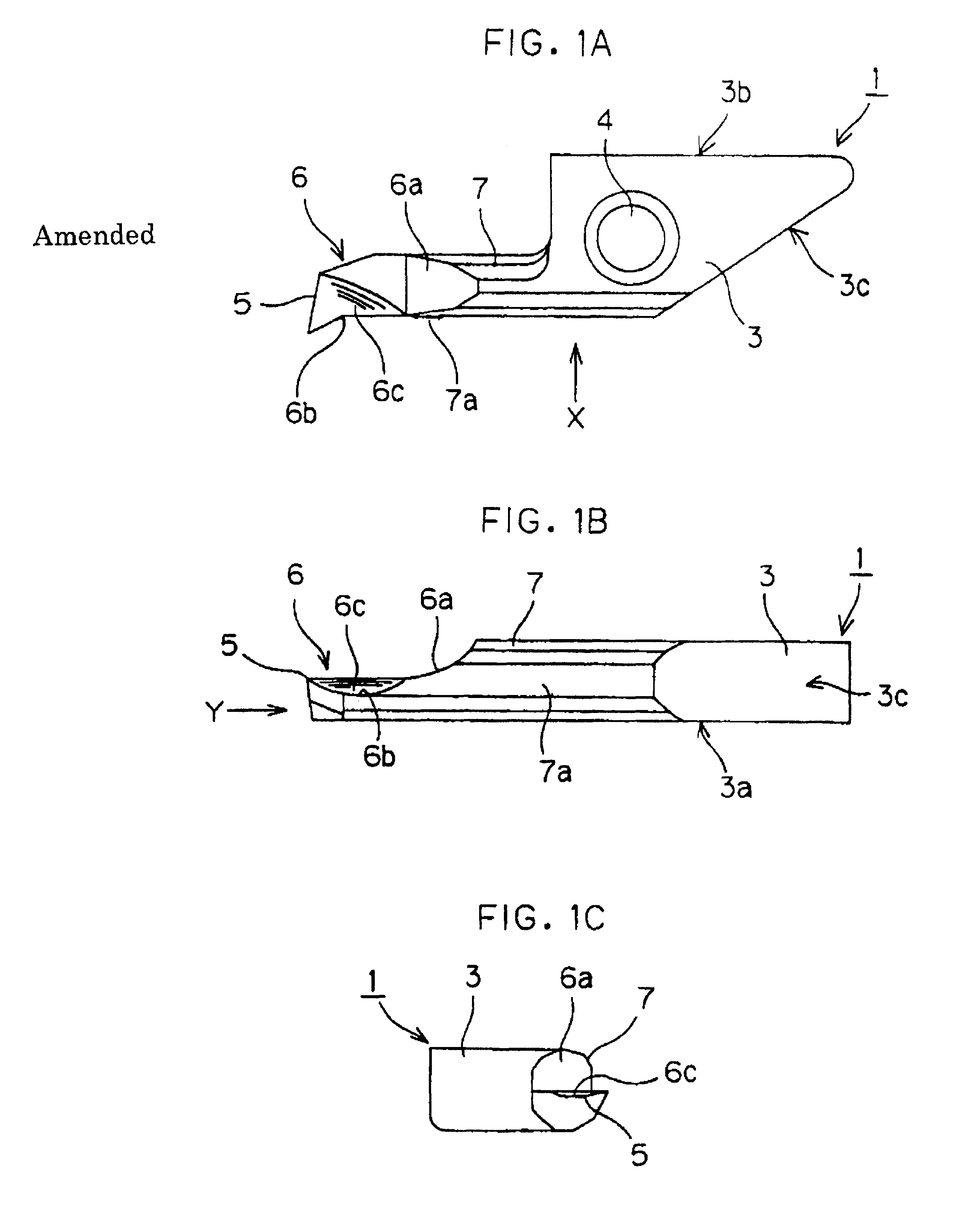
[0029]FIG. 1A is a top plan view of an indexable insert 1 according to one embodiment of the present invention, FIG. 1B is a perspective view taken along a line X shown in FIG. 1A (a front view of the indexable insert 1), and FIG. 1C is a perspective view taken along a line Y shown in FIG. 1B (a left side view of the indexable insert 1).

[0030]Referring to FIGS. 1A to 1C, the indexable insert 1 has a flat plate-shaped base 3 at its rear (on the right side of FIGS. 1A and 1B). The base 3 comprises a bottom surface 3a which is abutted, when it is attached to a holder, described later, against the holder, and a first side surface 3b and a second side surface 3c. The first side surface 3b and the second side surface 3c extend so as to cross each other in an acute-angled manner at the rear. Near the center of the base 3, a bolt hole 4 through which a bolt is to be passed is formed along the thickness of the base 3.

[0031]A stick-shaped portion 7 extends toward a front end of the indexable ...


PUM

PropertyMeasurementUnit
acute-angleaaaaaaaaaa
thicknessaaaaaaaaaa
acute angleaaaaaaaaaa

Abstract

The indexable insert of the present invention has a cutting edge at the end of a stick-shaped portion projecting from a tool base. The base is shaped to ensure effective clamping, thereby avoiding chatter and backlash. A cutting edge and a rake face are provided at the end of the stick-shaped portion, which is also provided with a side relief face so that chips cut from the workpiece are smoothly carried away. The cutting edge extends sideways beyond the side relief face so that the insert can effectively cut the walls of small and deep holes.

Description

[0001]This application is based on an application No. 10-245675 filed in Japan, the content of which is incorporated hereinto by reference.BACKGROUND OF THE INVENTION[0002]1. Field of the Invention[0003]The present invention relates generally to an indexable insert for cutting processing and a cutting tool having the indexable insert. More specifically, it relates to an indexable insert and a cutting tool having the indexable insert suitable for inner diameter processing of a small hole or a very small hole in a small-sized component such as a component for OA equipment, an electronic component, or a small diameter bearing.[0004]2. Description of the Prior Art[0005]Conventionally used as an inner diameter processing tool have been a throwaway type in which a chip 22 is fastened to a front end of a holder 21 so as to be attachable or detachable as shown in FIG. 6 and a brazing type in which a chip 32 is fastened by brazing to a front end of a holder 31 as shown in FIG. 7.[0006]The br...

Claims


Application Information

Patent Timeline
Patent Type & Authority Patents(United States)
IPC IPC(8): B23B27/02B23B27/00B23B27/16B23B29/03
CPCB23B27/007B23B27/141B23B27/16B23B2220/04Y10T407/2282Y10T407/2288Y10T407/245Y10T407/235B23B2270/20B23B27/00
Inventor TSUDA, YUUICHITAKAYANAGI, KIYOTADAKAWASAKI, TAIRAKUBO, HIROAKIHOKAKOBA, TOSHIHISA
Owner POLY TEC PROD
Why Eureka
Try Eureka