[0012]It is an object of the present invention to overcome, or at least reduce, the problems associated with the manufacture of conventional protective material and with protective wear made therefrom.
[0016]Such a flexible material can confirm more easily to the body of the wearer than conventional materials, as it is flexible in all three dimensions. It is therefore more comfortable to wear and can accommodate movement better than conventional materials. When used as a protective material or to form protective wear a single size, or a reduced number of sizes, can fit many different sized bodies.
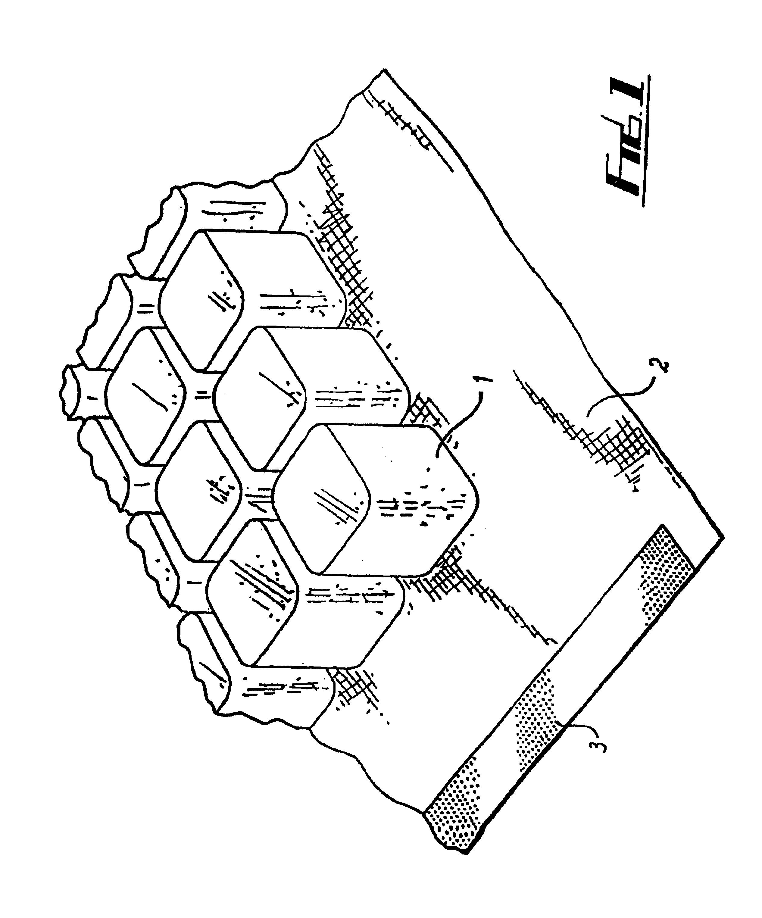
[0017]As the elements are separate and spaced apart; this facilitates flexing of the substrate to form a curved surface and enables the material to flex in all directions without “locking up” or preventing movement in a particular direction. This is a particular
advantage the flexible material of the present invention has over prior art arrangements which tend not to exhibit universal flexibility.
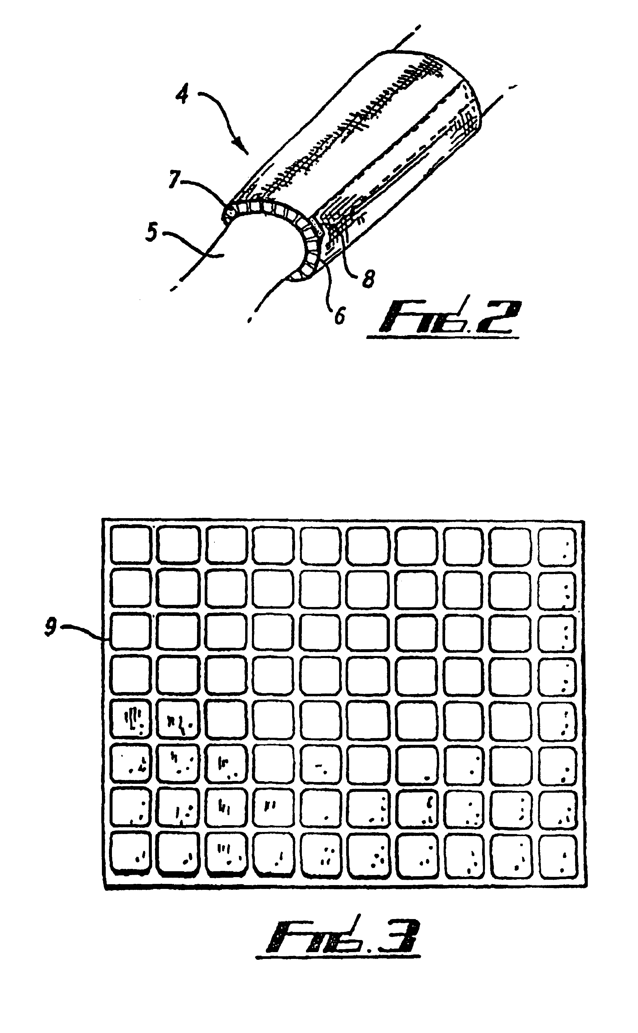
[0020]The elements preferably take the form of blocks. They can be of regular or
irregular shape, for example hexagonal or octagonal in cross-section. The elements are preferably evenly distributed on the substrate with a density of between 100 and 8000 elements / m2, more preferably between 250 and 8000 elements / m2, and still more preferably between 4000 and 6000 elements / m2. In one embodiment, the elements comprise cubes of side 12 mm spaced apart by 2 mm. This gives a density of about 5000 cubes / m2. This allows the material to flex easily along all directions, an improvement over known quilted protective materials. Also, one type of material can be
cut to many different sizes, for example to form protective wear of different sizes, without significantly affecting its ability to flex. This is in contrast to known quilted protective materials wherein due to the size of the foam strips, the size of each strip must be changed to form an article of different size without reducing flexibility.
[0024]The material could also be comprised in furniture or upholstery and can be particularly useful when used with wheelchairs and hospital beds. Spaced part elements can help to reduce the incidence of
bed sores. As the material is resilient, it comprises a
cushioning medium, for,; example for saddles. Where the material comprises a foam layer, this provides it with good thermally insulating properties and it can be usefully incorporated into, or used to form wet suits. A foam layer can also render the material buoyant in water, in which case it can be usefully used in or to form
buoyancy vests, life jackets and swimming aids. When used as a swimming aid, for example, the material can be incorporated in swimming costumes as an aid to the
buoyancy of the wearer. It is possible in this case to arrange for the foam blocks to be progressively removable from the costume as the confidence and skill or the trainee swimmer increases.
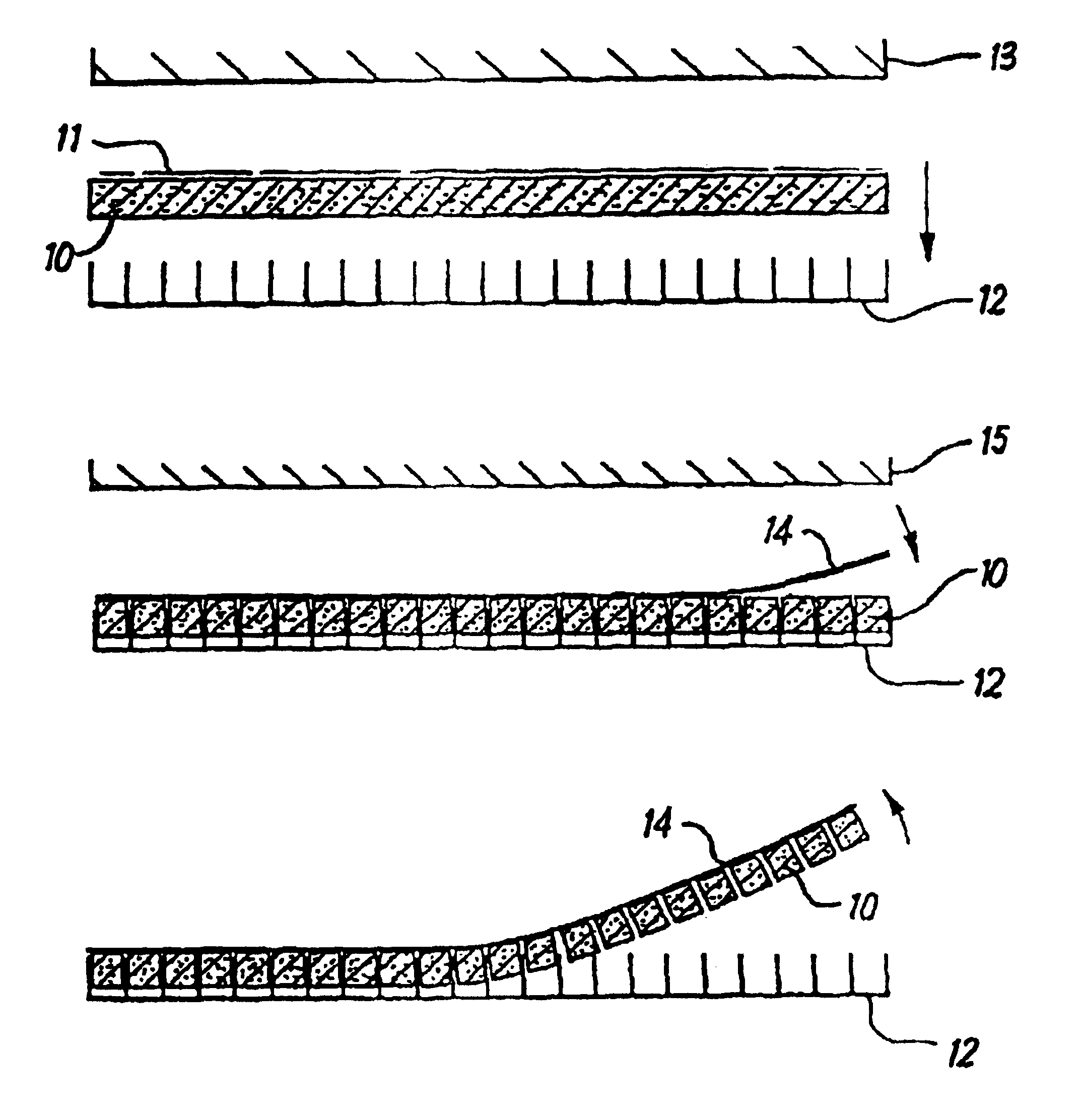
[0029]Advantageously, the resilient sheet is
cut into a plurality of separate elements using a cutter which acts as the jig after
cutting through the resilient material to hold the elements in place while the substrate layer is applied thereto. Preferably, the cutter is adapted so that said one side of each, now
cut, element are made to stand proud of the surface of the cutter grid. The
sheet material may spring back slightly after
cutting to accomplish this. Alternatively, means, such as ejectors, are provided to achieve this effect.

