Information transmission system using light as communication medium, information transmission method, image pickup device, and computer programmed product

a technology of information transmission system and light source, which is applied in the field of information transmission system using light source as communication medium, information transmission method, image pickup device, and computer programmed product, can solve the problems of complex information coding, inability to easily understand the relationship between information presentation and information presenting object, and inability to simplify complex information coding, so as to prevent adverse effects

Inactive Publication Date: 2011-10-18
CASIO COMPUTER CO LTD
View PDF8 Cites 85 Cited by
  • Summary
  • Abstract
  • Description
  • Claims
  • Application Information

AI Technical Summary

Benefits of technology

[0008]It is an object of the present invention is to provide an information transmission system that prevents adverse effects caused by disturbance light in information transmission using light as a communication medium to make it possible to perform transmission and reproduction of accurate information at all times, and an information transmission method, and an image pickup device.

Problems solved by technology

(1) In the case where the number of information presenting objects is large, the number of information presentations such as signboards, etc increases, resultantly, main object does not become conspicuous. Moreover, the relationship between the information presentation and the information presenting object cannot be easily understood. Erroneous understanding of information occurs in some cases. For example, there is a case in which information on goods A is misunderstood as information on goods B.
(2) Character information written on the information presentation can be read by anyone who has normal eyesight. For this reason, in order to present limited information (for example, purchasing cost of goods, maximum reduction rate, etc.,) to only specific persons, it is necessary to take protection measures such as information coding, and so on. However, complicated information coding has to be simplified since the usability is bad, and this causes a possibility that the effect of information coding will be reduced and that such information will be easily read.

Method used


Image

  • Information transmission system using light as communication medium, information transmission method, image pickup device, and computer programmed product
  • Information transmission system using light as communication medium, information transmission method, image pickup device, and computer programmed product
  • Information transmission system using light as communication medium, information transmission method, image pickup device, and computer programmed product

Examples


first embodiment

[0086](First Embodiment)

[0087]A specific explanation is next given of a first embodiment to which the present invention is applied. FIG. 4 is a view showing the light emitting unit and light receiving unit, and 4A is a front perspective view of the light emitting unit 30, 4B is a front perspective view of the light receiving unit 40, and 4C is a rear perspective view of the light receiving unit 40. The light emitting unit 30 is structured such that a light emitting window 32 is attached to an outer case 31 with an appropriate shape (preferably an outer case with a drip-proof construction suitable for outdoor installation). Further, the light receiving unit 40 is an image pickup device, such as a digital camera, which is structured such that an optical lens section 42, a shutter key 43, and a liquid crystal display 44 are attached to a body 41 with a shape suitable for hand-holding.

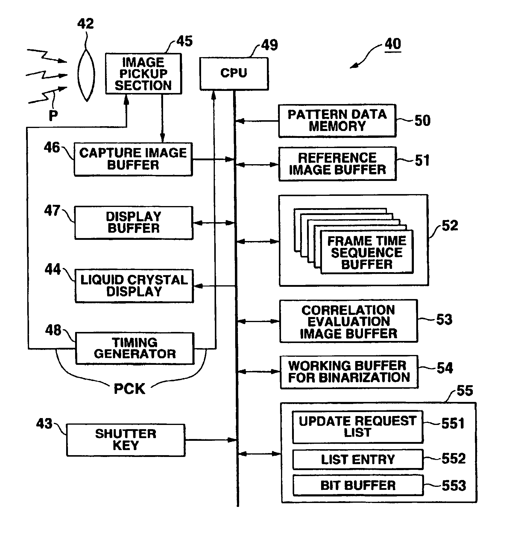
[0088]FIG. 5 is a structural view of an electrical interior of the light emitting unit 30 and the light...

second embodiment

[0146](Second Embodiment)

[0147]In the aforementioned first embodiment, an image with 40 frames (8×5 frames) at the minimum is required in order to transfer one character (use of non-compressed 8-bit code text data is assumed).

[0148]Accordingly, for example, such a disadvantage causes that time of 1.33 per sec. is required to transfer one character and more time is needed with an increase in the number of characters.

[0149]In order to avoid such a disadvantage, it is desirable that a frame rate should be simply increased. However, if the frame rate is set to 30 fps (frame / second) to obtain a 10-fold transfer rate, a frame rate of 30×10=300 fps will be required.

[0150]Further, a case may be considered that the number of dots for frame image is reduced in order to decrease the amount of data processing while increasing the frame rate (for example, if the amount of data is set to 1 / 10 in a state of 300 fps, an area to be detected may be reduced to a degree of, e.g., 228×152 dots, which is...

third embodiment

[0178](Third Embodiment)

[0179]In the third embodiment, attention is paid to the point that the image pickup device using CMOS sensor as an image element includes a “sampling mode” function, and the vertical and horizontal lines are sampled every one dot in the same field angle to increase the frame rate.

[0180]“Sub-sampling (or sub-sampling compression method)” in the “sampling mode” function is one type of irreversible image compression algorithms. In other words, this is the method that reduces dots with suitable intervals to provide processing to the pixels instead of the method that provides processing to all pixels in the field angle.

[0181]FIG. 23 is a structural view of an electrical interior of the light receiving unit 40 according to a third embodiment.

[0182]In order to make full use of the above “sub-sampling mode” function, the third embodiment includes a sub-sampling control memory 111, which holds control information on the “sub-sampling mode” function, and a reading cond...


PUM


Abstract

A CPU 36 of a light emitting unit 30 fetches ith bit of transmission information TX stored in a transmission data memory 33 in synchronization with a clock signal CK from a timing generator 35. The CUP 36 determines the bit value and fetches a first pattern sequence SA from a pattern data memory 44 when the bit is logic signal 1, and fetches a second pattern sequence SB from a pattern data memory 34 when the bit is logic signal 0, and outputs the first pattern sequence SA and second pattern sequence SB to a light emitting section 37. While, a CPU 39 of a light receiving unit 40 extracts a pixel area with a time sequence luminance variation pattern from a frame image captured into a capture image buffer 46, and binarizes the luminance variation pattern, and performs logic determination. A liquid crystal display 44 displays information of a light emitting area to be overlapped with a subject image.

Description

[0001]Notice: More than one reissue application has been filed for the reissue of U.S. Pat. No. 6,933,956. The reissue applications are the present application and application Ser. No. 13 / 044,441, filed on Mar. 9, 2011, which is a Divisional Reissue Application of the present application.BACKGROUND OF THE INVENTION[0002]1. Field of the Invention[0003]The present invention relates to an information transmission system available for displaying the explanation of commodity products at the store, explanation of exhibit products at a museum, an exhibition, and for displaying landmarks and advertisements of building, etc., crowd state of amusement facilities such as an-amusement park, and relates to an information transmission method, an image pickup device, and a computer programmed product.[0004]2. Description of the Related Art[0005]Conventionally, display for information relating to commodity and exhibit products, display for landmarks and advertisements of building, etc., display for...

Claims


Application Information

Patent Timeline
Patent Type & Authority Patents(United States)
IPC IPC(8): G09G5/10H04N5/232G09F27/00G06F3/147H04B10/11
CPCG06F3/147H04B10/11G09G2370/16
Inventor SATO, KUNIOIIZUKA, NOBUO
Owner CASIO COMPUTER CO LTD
Why Eureka
Try Eureka