
Transmitting advertisements to smart cards

A chip card, chip technology, used in the field of data or transaction cards to reduce long-term costs, reduce paperwork, and avoid the need for

Inactive Publication Date: 2007-10-03
SAMSUNG ELECTRONICS CO LTD
View PDF21 Cites 0 Cited by
  • Summary
  • Abstract
  • Description
  • Claims
  • Application Information

AI Technical Summary

Problems solved by technology

For example, long-distance carriers can only provide chips that operate on their remote equipment

Method used


Image

  • Transmitting advertisements to smart cards
  • Transmitting advertisements to smart cards
  • Transmitting advertisements to smart cards

Examples


Embodiment Construction

[0048] Detailed Description of Preferred Embodiments

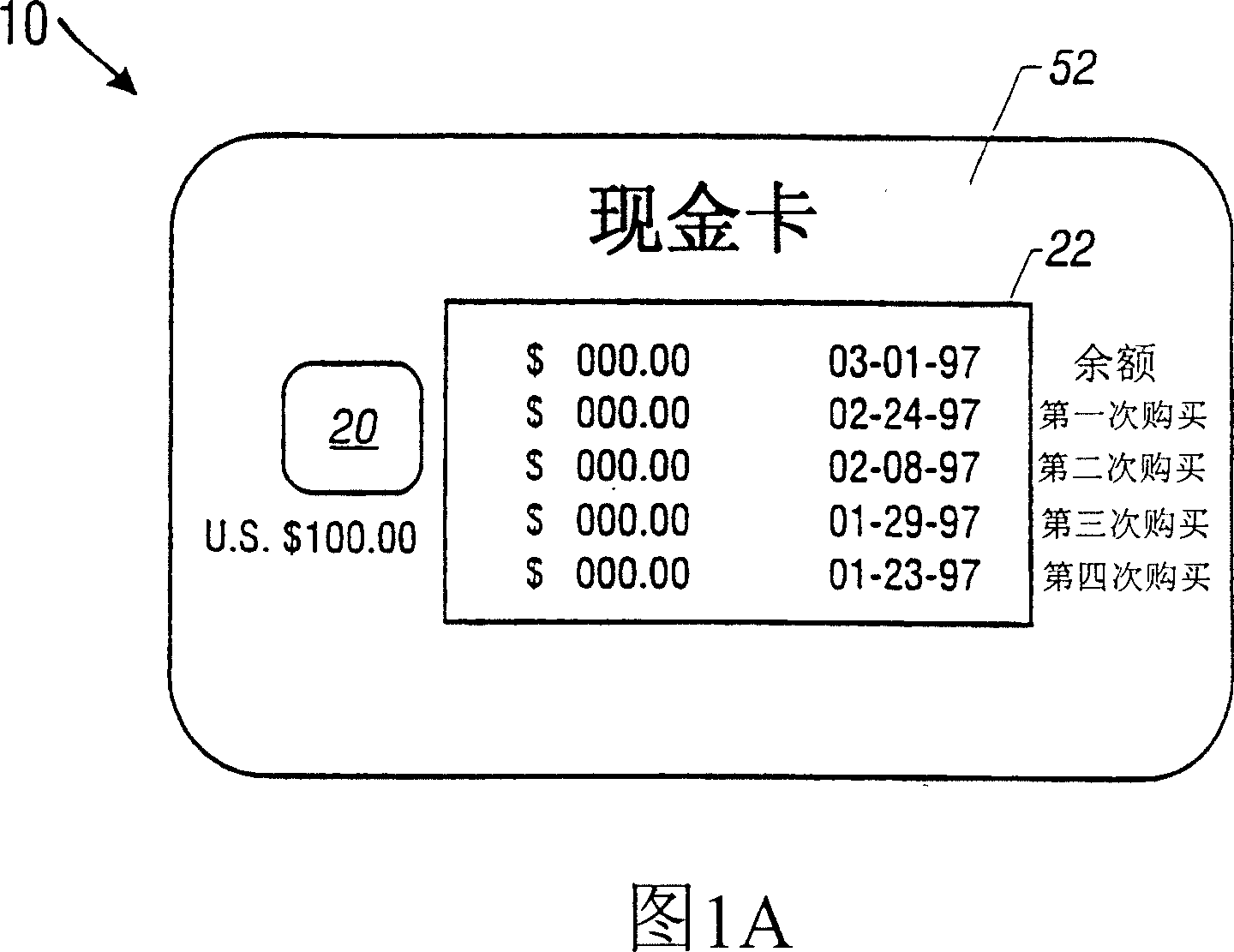
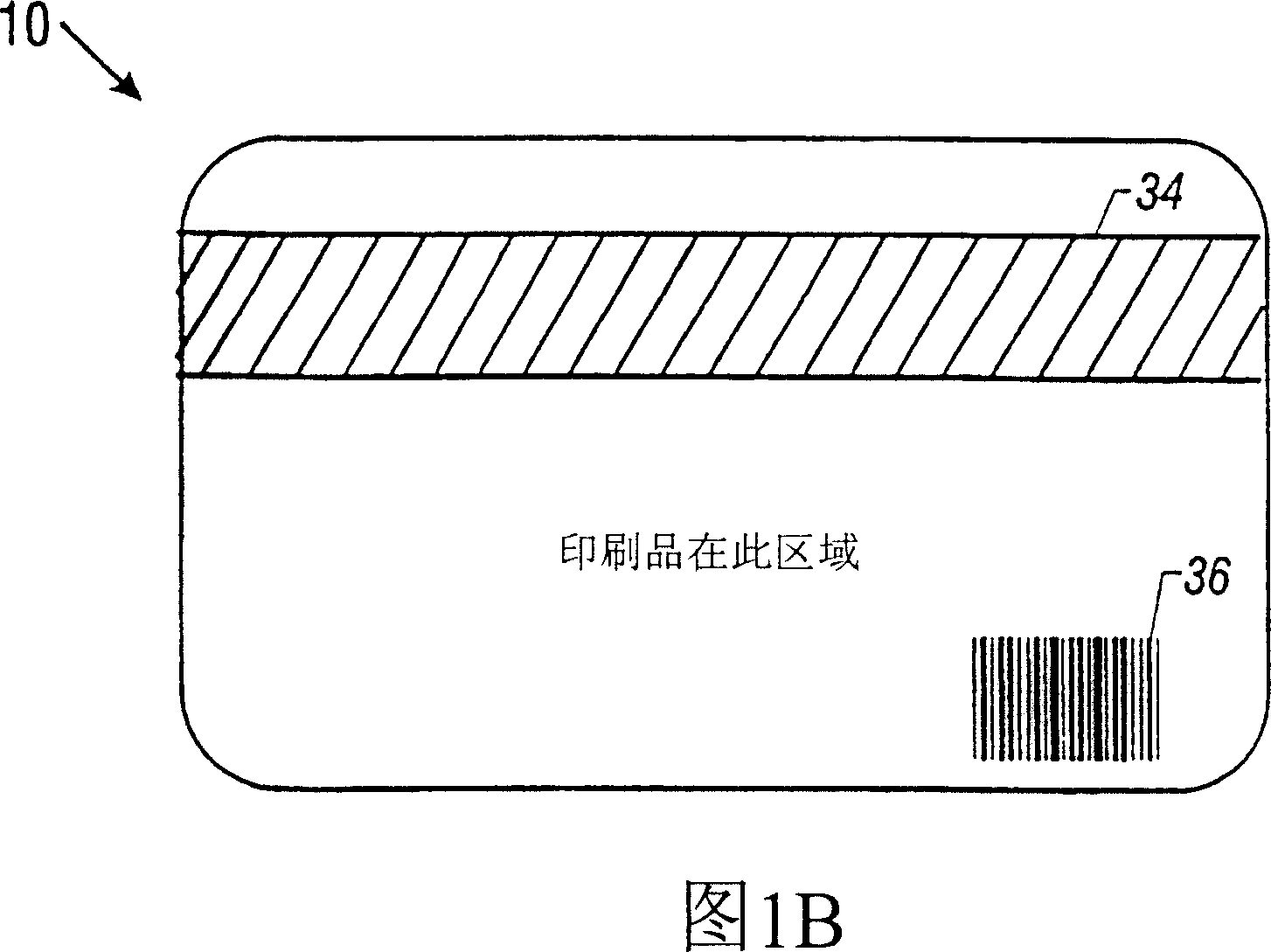
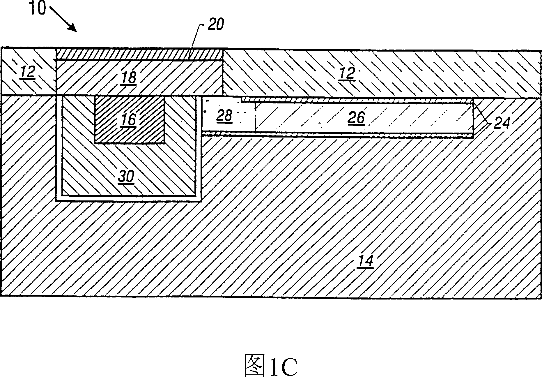
[0049] Referring now to Figures 1A-1C, a chip card 10 is shown having a transparent protective top layer 12 (PVC or other transparent plastic) and a transparent (opaque or translucent) substrate 14 (PVC or other plastic). The top layer and substrate (body) can be molded or machined into the desired shape to accommodate the card's internal components. The indicia is printed on the top layer (eg inner surface) and holograms (not shown in Figs. 1A-1C, see 32 in Fig. 3) may be mounted on the underside of the top layer (eg rainbow holographic elements often used in credit cards). On the bottom of the card (FIG. 1B) is provided a conventional magnetic strip 34 and a signature strip.

[0050] An integrated circuit 16 is mounted on the underside of a printed circuit board 18, secured in a cutout portion of the card body. The contact 20 completely covers one surface of the printed circuit board, and the contact 20 is exposed outs...


PUM


Abstract

A flexible chip card (100) has a flexible display (114a), and a power source (38), is used in a system which transmits various information for storage and later retrieval. The liquid crystal display (114a) may be of the bistable type, requiring no power to continuously display an image. The display may include a barrier strip to provide stereoscopic effects. The chip card (100) may be used to store coupons, advertisements, tickets, internet addresses, images, audio data, and other information.

Description

Background of the invention [0001] The present invention relates to data or transaction cards containing semiconductor processors and / or memory chips. [0002] Such cards are often referred to as chip cards (or smart cards). They are usually the size of a wallet and contain a microchip. The surface of the card generally has electrical contacts via which communication is established between the external chip card device and the semiconductor chip. But there are also wireless chip cards, in which a wireless transceiver is used for communication. Today, chip cards are used in a variety of fields, including telecommunications, government programs, health care, public transport, universities and vending machines. [0003] One type of chip card in widespread use today is a stored-value card, in which a microchip embedded in the card contains a currency amount. For example, each time a consumer uses a chip card at a vending machine, the amount of the purchase is subtracted from t...

Claims


Application Information

Patent Timeline
Patent Type & Authority Patents(China)
IPC IPC(8): G06K19/07G02F1/13G02F1/1333G06K19/077G07F7/08G09F23/00G09F27/00
CPCG06K19/0723G06K19/07749G02F1/13452G06Q20/3574G06Q20/363G06Q20/045G07F7/0873G06Q20/341G06K19/07703G06Q20/352G06Q20/347G07F7/0866G02F1/133305G06K19/07
Inventor 加里·A·弗里曼戴维·H·弗里曼
Owner SAMSUNG ELECTRONICS CO LTD
Learn More