Tube mould for continuous casting

An ingot mold and continuous casting technology, which is applied in the field of tubular ingot molds, achieves the effects of high processing speed, increased output, and convenient clamping

Active Publication Date: 2007-10-24
CONCAST AG
View PDF9 Cites 0 Cited by
  • Summary
  • Abstract
  • Description
  • Claims
  • Application Information

AI Technical Summary

Problems solved by technology

[0004] However, in addition to the cooling capacity for a given casting pattern which can have a direct impact on the output of each casting, the durability of the ingot mold also constitutes an important cost factor for the economics of the continuous casting plant

Method used


Image

  • Tube mould for continuous casting
  • Tube mould for continuous casting
  • Tube mould for continuous casting

Examples


Embodiment Construction

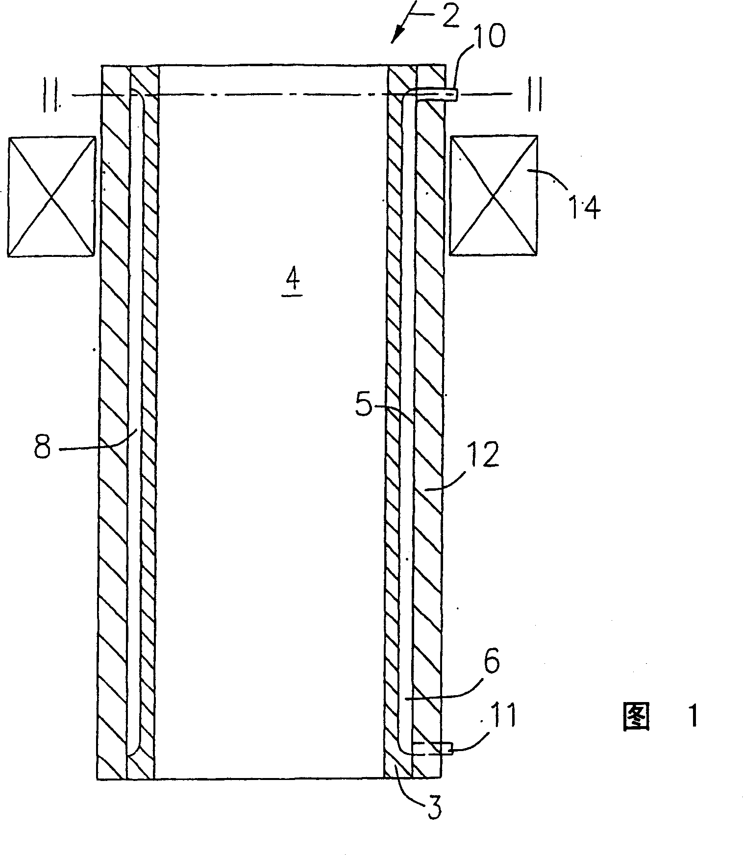
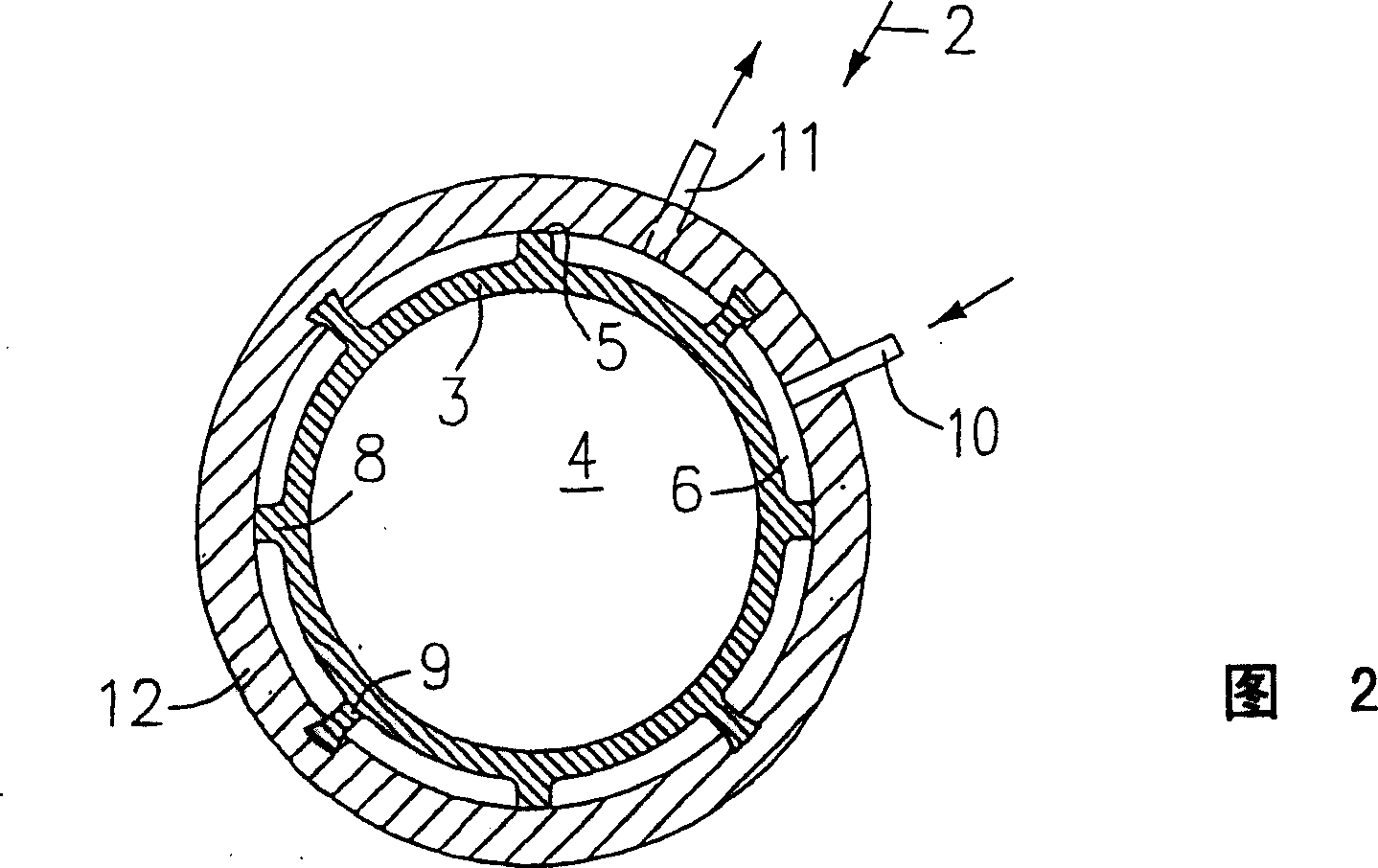
[0028] In FIGS. 1 and 2 , a continuous casting mold for round billets or blooms is indicated by 2 . A copper tube 3 forms a cavity 4 . A water circulation cooling system for the copper tube 3 is arranged outside the copper tube 3 forming the tube outer side 5 . This water circulation cooling system consists of cooling channels 6 distributed over the entire circumference and essentially the entire length of the copper tube 3 . The individual cooling channels 6 are delimited by supporting and connecting flanges 8 and 9, the other task of which is to guide the cooling water circulation in the cooling channel 6 from a water supply pipe 10 into a The drainage pipes 11 and 12 designate a support shell which surrounds the copper tube 3 over its entire circumference and over its entire length and which supports the copper tube 3 on the outer side 5 of the tube via a support flange 8 . The connection flange 9 connects the copper pipe 3 to the support shell 12 . The support shell 12 ...


PUM


Abstract

Moulds are used for continuously casting round or polygonal billet and preblock formats, wherein the mould cavity thereof is made of a copper pipe (3) which is intensively cooled by means of a water circulation cooling system. According to the invention, in order to increase both the cooling capacity and the dimensional stability of the mould cavity (4) and to increase the total service life of the copper pipe (3), the copper pipe (3) is provided with a protective casing (12) or protective plates which cover the entire periphery of the outer pipe casing (5). Cooling channels (6) which are used to guide the cooling water to the copper pipe (3) or to the protective casing (12) are provided in order to cool the copper pipe (3). The cooling channels (6) are distributed over the entire periphery on the outer pipe casing (5) and extend essentially over the entire length of the mould.

Description

technical field [0001] The invention relates to a tubular ingot mold for the continuous casting of round and polygonal blank and bloom cross-sections. Background technique [0002] Tubular ingot molds are used for the continuous casting of steel into billets and small bloom cross-sections. This tubular ingot mold consists of a copper tube fitted in a water jacket. In order to achieve circulating cooling of the cooling water at a high flow rate, a tubular drainer is arranged outside the copper pipe with a small gap relative to the copper pipe. Cooling water is punched between the drain and the copper pipe at a high pressure and a high flow rate of up to 10m / s and above on the entire circumference of the copper pipe. In the casting process, in order to prevent any destructive deformation of the copper tube due to the large temperature difference between the cavity side and the cooling water side, the copper tube, which is basically only held by flanges at the lower and upper...

Claims


Application Information

Patent Timeline
Patent Type & Authority Patents(China)
IPC IPC(8): B22D11/00B22D11/04B22D11/055
CPCB22D11/04B22D11/055B22D11/00B22D11/124B22D11/115H01F7/02H01F7/06
Inventor A·勒里希F·卡瓦
Owner CONCAST AG
Why Eureka
Try Eureka