Motor

A motor and housing technology, applied in the field of motors, can solve the problems of reduced magnetic saturation feed accuracy, limited use environment, large leakage magnetic flux, etc.

Inactive Publication Date: 2007-10-31
SANKYO SEIKI MFG CO LTD
View PDF3 Cites 0 Cited by
  • Summary
  • Abstract
  • Description
  • Claims
  • Application Information

AI Technical Summary

Problems solved by technology

[0006] However, when such a structure is adopted, the leakage magnetic flux from the opening 20 is large, and the environmental resistance due to the intrusion of moisture through the opening 20 is lowered, so there is a problem that the use environment is limited.
In addition, although the housing 2 itself bears a part of the magnetic circuit, when the opening 20 is formed on the housing 2, there are also problems that magnetic saturation, torque and feed accuracy are easily reduced due to the length of the magnetic circuit.

Method used


Image

  • Motor
  • Motor
  • Motor

Examples


Embodiment Construction

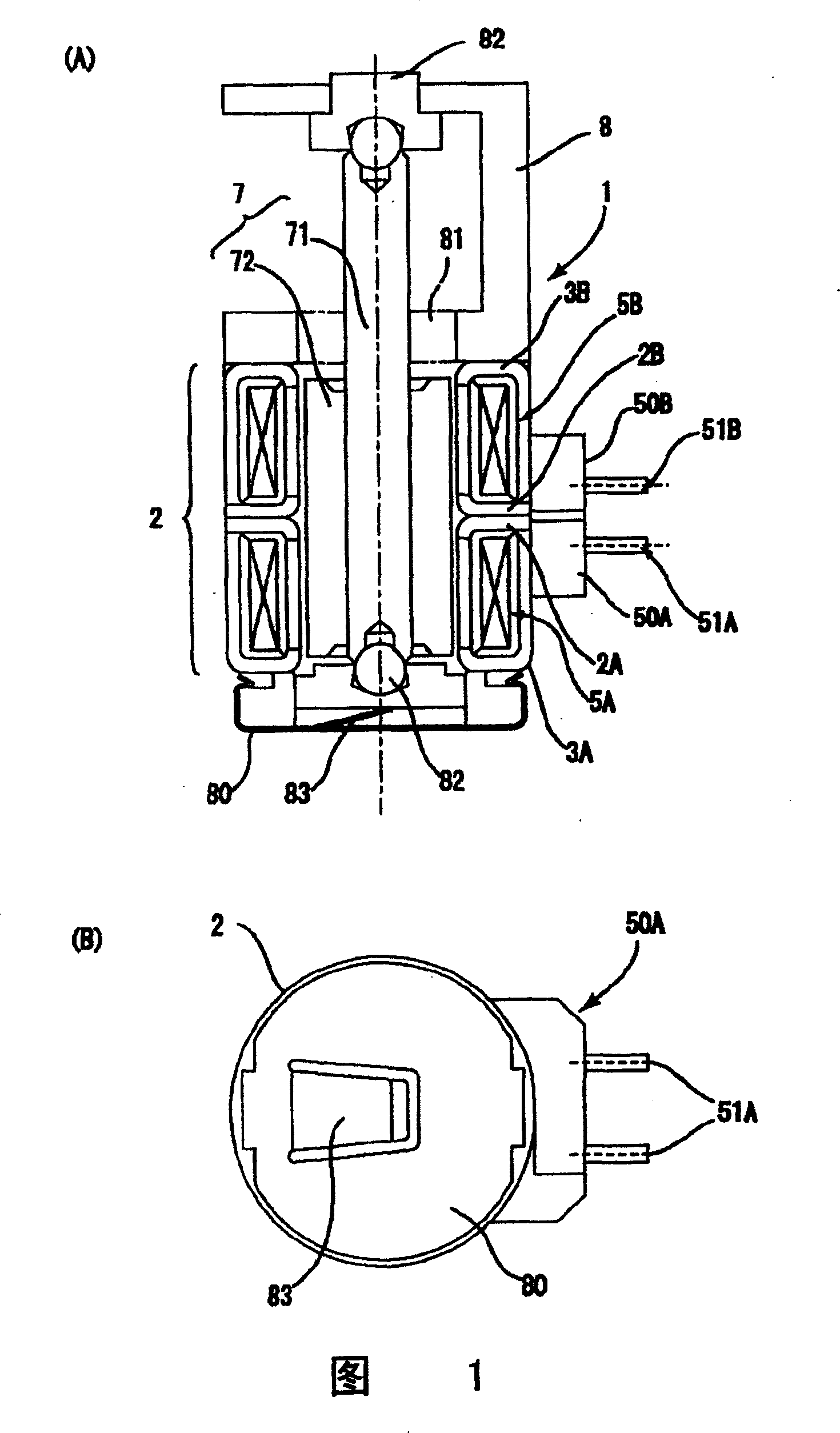
[0019] Embodiments of the present invention will be described with reference to the drawings. In addition, since the basic structure of the stepping motor to which the present invention is applied is also described with reference to FIG. 1(A), description of the basic structure will be omitted, and only the characteristic parts will be described below.

[0020] [Embodiment 1]

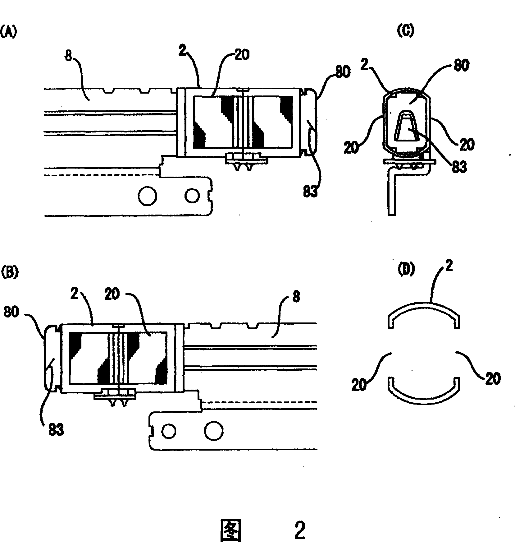
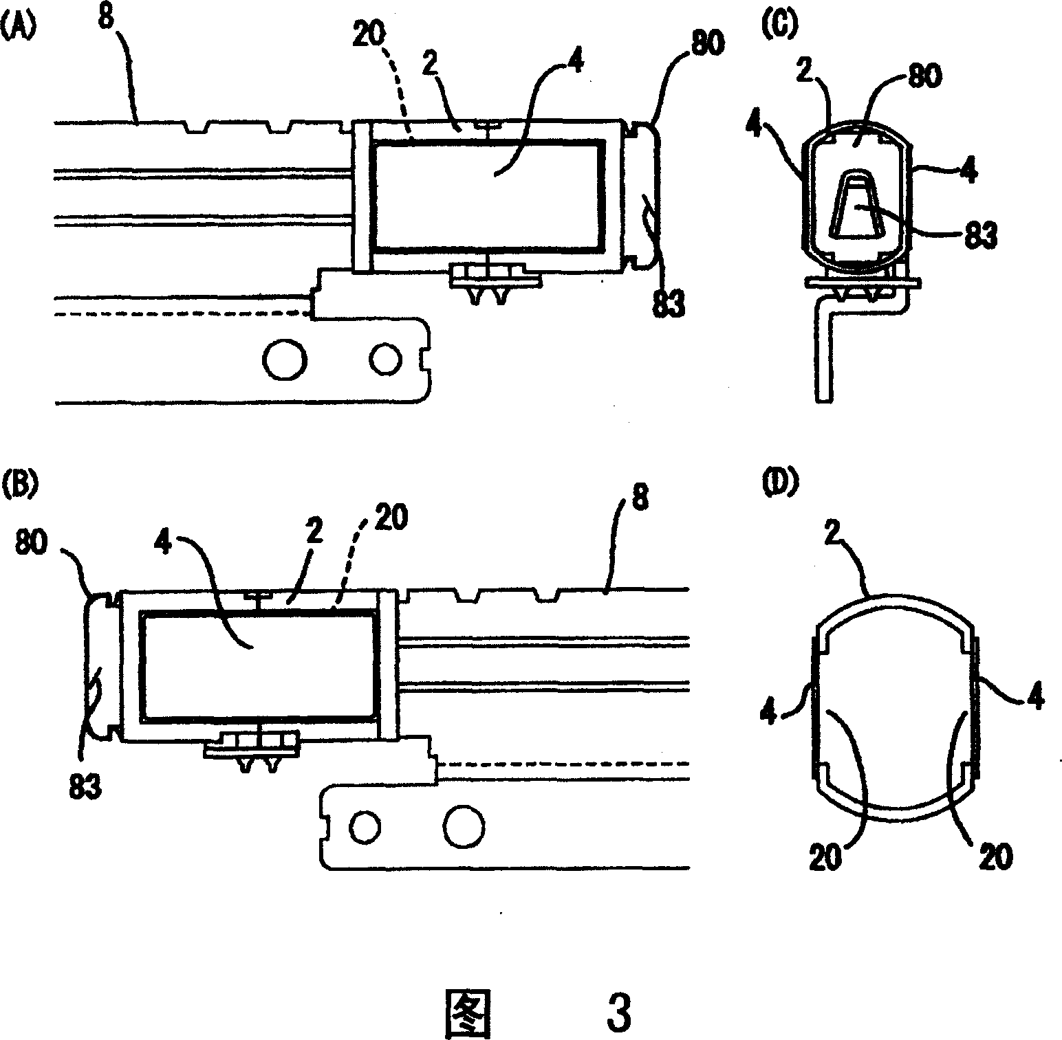
[0021] Fig. 2 (A), (B), (C), (D) are the left side view, the right side view, the bottom view and the casing of the state that the opening is formed on the side of the casing in the stepping motor shown in Fig. 1 respectively. A cut-away end view cut in a direction perpendicular to the motor axis. 3(A), (B), (C), and (D) are left side views showing the state in which the opening formed in the side surface of the casing is covered with a magnetic plate in the stepping motor according to Embodiment 1 of the present invention, respectively. , right view, bottom view and cut-off end view after cutting the...


PUM


Abstract

This stepping motor 1 is formed with a rectangular opening 20 at each of right and left sides of a case 2. The opening is covered with a thin magnetic plate 4 made of a permalloy. One of two magnetic plates 4 is formed with an extension portion 40 which is bent from the side to the bottom of the case 2, and extends to the end of a rotating shaft 71 of a rotor. The extension portion 40 is partially cut and raised, and formed with a spring 41 for forcing the rotating shaft 71 in the axial direction of the motor.

Description

technical field [0001] The present invention relates to electric motors, and more specifically, relates to the technology of thinning the casing of electric motors. Background technique [0002] As shown in Fig. 1 (A), (B), the small-sized stepping motor 1 that is used for digital camera, digital video camera, elongated ODD etc., the ring-shaped first bobbin 5A and the second coil frame 5A after the winding of its coil The coil frame 5B is generally arranged overlappingly in the axial direction of the motor. In the rotor arrangement hole formed by the first coil frame 5A and the second coil frame 5B, a plurality of pole teeth of the inner stator 2A, 2B and the outer stator 3A, 3B It is a structure arranged in the circumferential direction. In the rotor 7, a rotor magnet 72 is fixed around a rotating shaft 71, and the rotor magnet 72 faces the pole teeth of the stator through a predetermined gap in the rotor arrangement hole. A plate 8 is fixed to the outer stator 3B, and t...

Claims


Application Information

Patent Timeline
Patent Type & Authority Patents(China)
IPC IPC(8): H02K37/14H02K1/14H02K5/02H02K5/04
CPCH02K5/04H02K1/145
Inventor 西村清志小川吉典
Owner SANKYO SEIKI MFG CO LTD
Why Eureka
Try Eureka