Method of manufacturing optical glass elements

A manufacturing method and technology of optical elements, applied in the fields of optical elements, glass pressing, glass manufacturing equipment, etc., can solve the problems of unavailable glass optical elements and changes in the refractive index of glass molded products, so as to improve productivity and shorten molding cycle Time, the effect of preventing deterioration of surface accuracy

Active Publication Date: 2007-11-14
HOYA CORP
View PDF4 Cites 0 Cited by
  • Summary
  • Abstract
  • Description
  • Claims
  • Application Information

AI Technical Summary

Problems solved by technology

However, depending on the cooling conditions of the glass molded product after press molding, the refractive index of the glass molded product may change, and a glass optical element having a desired refractive index may not be obtained.

Method used


Image

  • Method of manufacturing optical glass elements
  • Method of manufacturing optical glass elements
  • Method of manufacturing optical glass elements

Examples


Embodiment 1

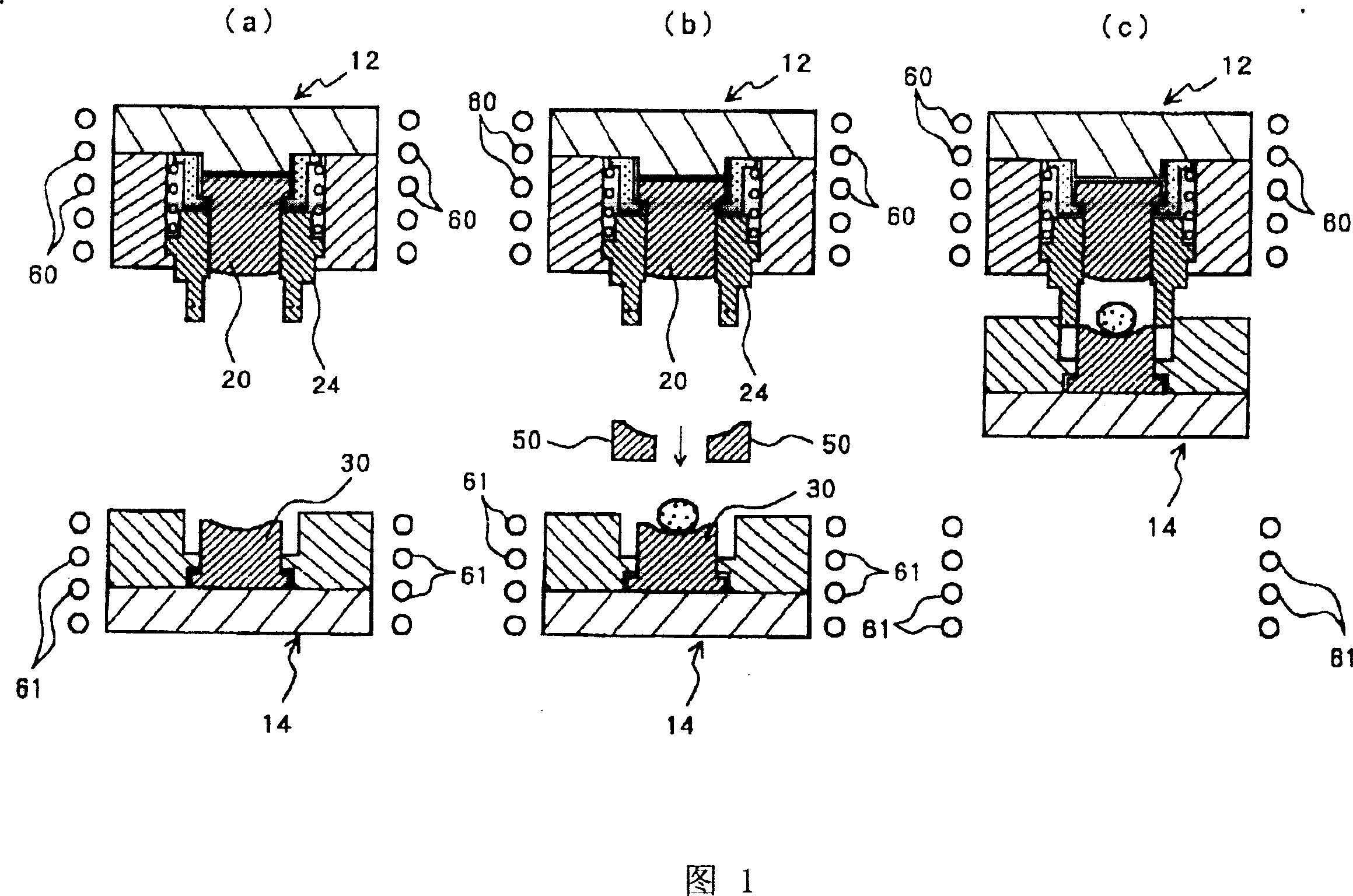
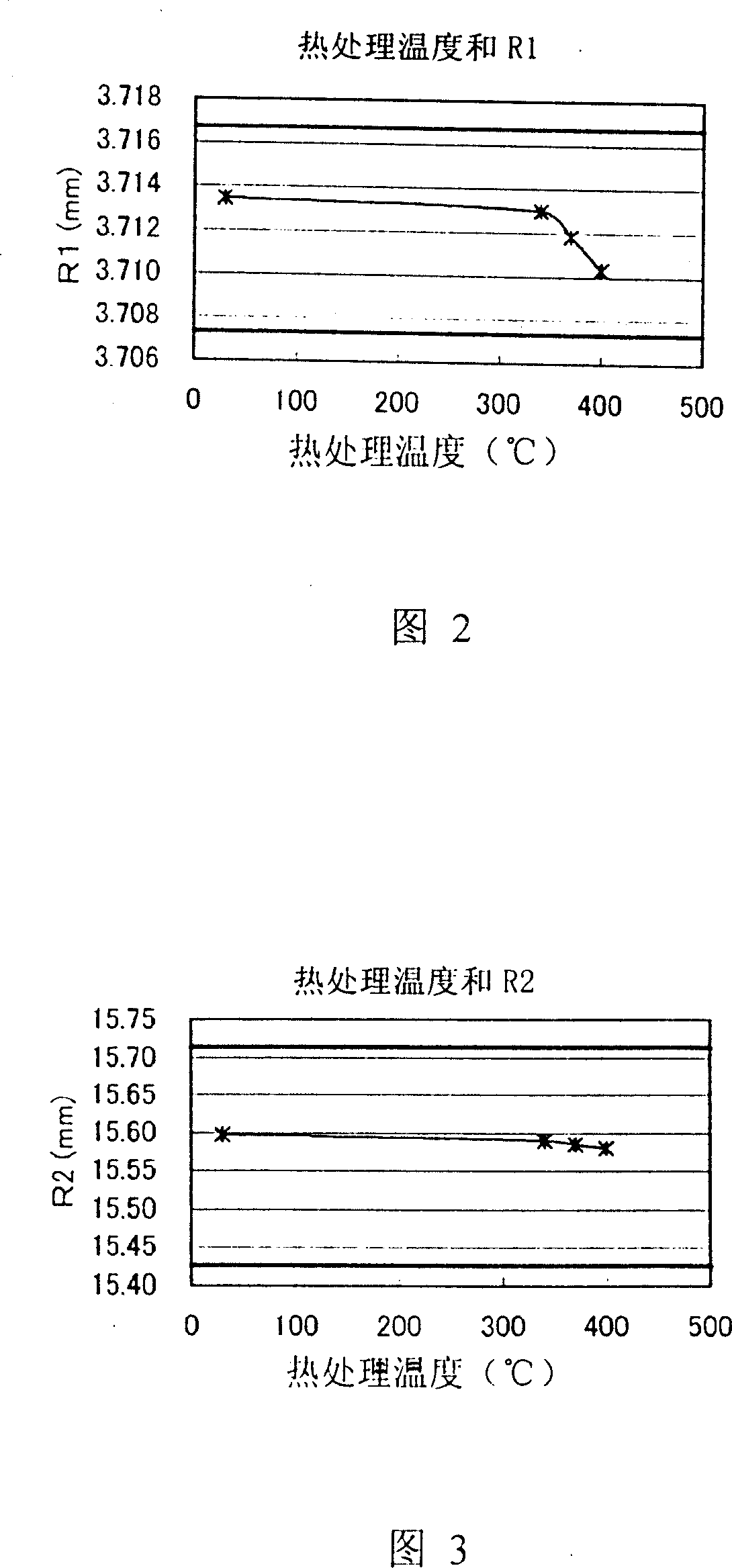
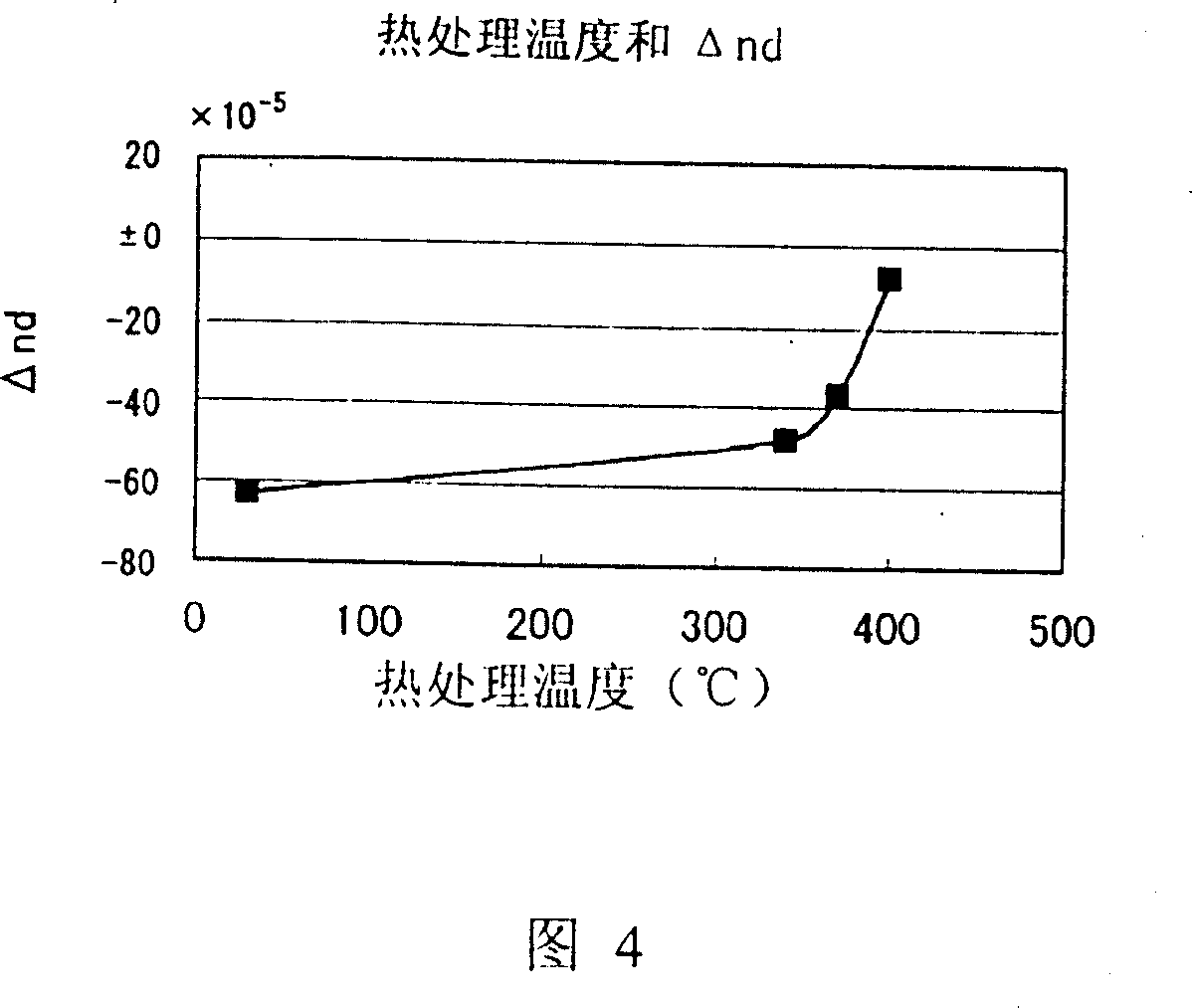
[0063]Borosilicate optical glass (Ts: 545°C, Tg: 515°C, strain point: 478°C) was used as the glass material, and a convex lens with a diameter of 7.0 mm and a central thickness of 1.25 mm was molded with the molding die shown in Fig. 1 . The stamping mold is formed by mirror-polishing the molding surfaces of the SiC profiles obtained by the CVD method on the upper and lower molds, and using the DLC film formed by the sputtering method as the mold release film. The upper and lower molds are respectively surrounded by tungsten alloy master molds that are susceptible to induction heating, and the upper and lower molds are heated by heat conduction using the master molds that are heated by high-frequency induction heating around them. The temperature of the upper and lower molds is controlled by an unillustrated electric heating pair inserted into the upper and lower molds.

[0064] In FIG. 1, at least one of the upper mold 20 and the lower mold 30 is movable. The lower die 30 mo...


PUM

PropertyMeasurementUnit
strain pointaaaaaaaaaa
thicknessaaaaaaaaaa
refractive indexaaaaaaaaaa

Abstract

A method of manufacturing optical glass elements by means of mold pressing, wherein a heat-softened glass material is press molded with a pressing mold to manufacture optical glass elements. The refractive index of the optical glass elements is precisely adjusted so that the manufactured optical glass elements exhibit predetermined refractive index.

Description

technical field [0001] The present invention relates to a manufacturing method for manufacturing glass optical elements by using a metal molding die to press and mold heated and softened glass raw materials to manufacture glass optical elements. In particular, it relates to the manufacture of glass optical elements capable of finely adjusting the refractive index of glass optical elements to have a desired refractive index. Background technique [0002] Using a molding die with a precision-machined molding surface, a method of stamping heated and softened glass raw materials to manufacture glass optical elements such as photographic lenses without a grinding process (glass mold stamping method), as a method that can mass-produce glass optical elements at low cost method has been used all the time. This method shortens the cycle time (the time required to manufacture a glass optical element) in order to increase productivity and shorten the cooling time of the glass molded p...

Claims


Application Information

Patent Timeline
Patent Type & Authority Patents(China)
IPC IPC(8): C03B11/00G02B3/00C03B11/08C03B11/12C03C23/00
CPCC03C23/007C03B2215/60C03B11/08C03B2215/48Y02P40/57
Inventor 广田慎一郎坂井裕之近江成明
Owner HOYA CORP
Why Eureka
Try Eureka