Coiling apparatus of yarn
A yarn winding machine and yarn technology, applied in spinning machine, textile and paper making, transportation of filamentous materials, etc. The effect of reducing the number of
- Summary
- Abstract
- Description
- Claims
- Application Information
AI Technical Summary
Problems solved by technology
Method used
Image
Examples
no. 1 example
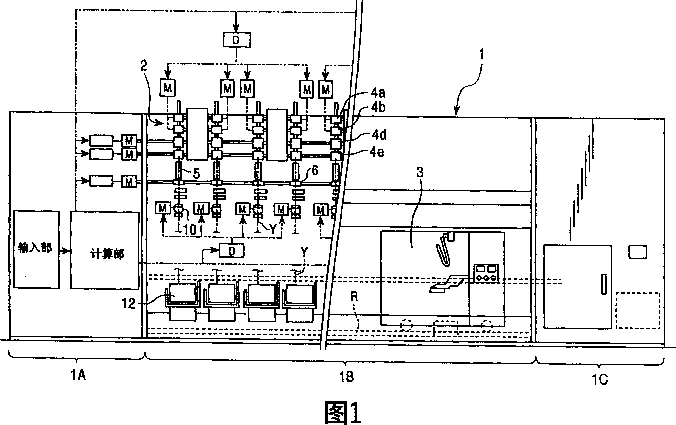
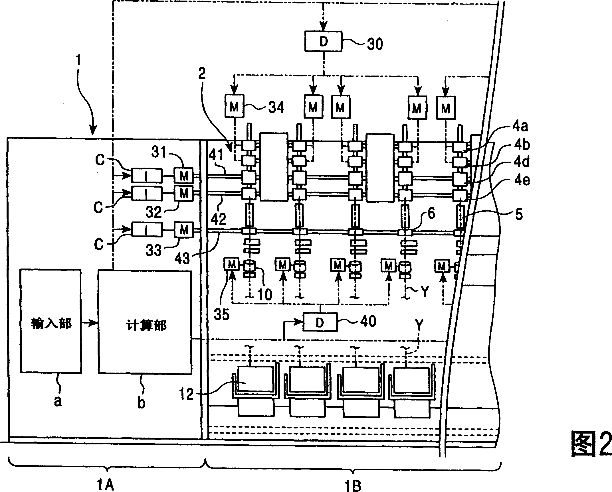
[0055] Fig. 1 is a front view of an example of a spinning machine 1 to which the present invention is applied. FIG. 2 is a schematic enlarged view of a part of the internal structure of the spinning machine 1 . The spinning machine is constituted by, for example, an air spinning machine. The main components of the spinning machine 1 include: a control section 1A; a spinning section 1B, in which a large number of spinning units 2 are arranged side by side; a blower section 1C; and a work trolley 3, which includes a yarn Splicing device, and can run freely between the spinning units 2 along the track R.
[0056] The control section 1A of the spinning machine 1 implements the following control: controlling the operation of the drive motors 31, 32, 33 of the drive shafts 41, 42, 43 for supplying all spinning units 2 constituting the spinning section 1B. Applying driving force; controlling the operation of the motors 34, 35 provided for each spinning unit 2; controlling the opera...
no. 2 example
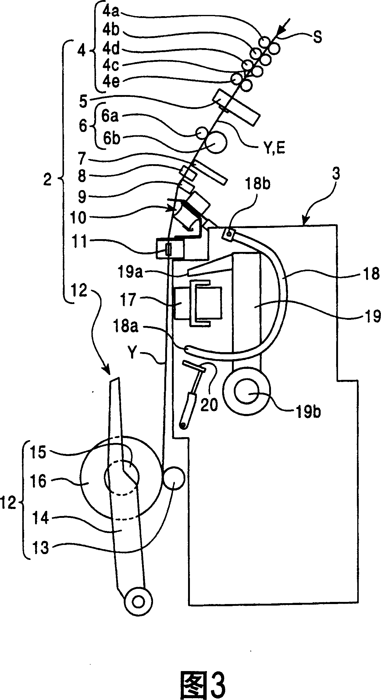
[0104] In the yarn slack eliminating device 10 according to the present invention, the upstream side guide 23 of the slack eliminating roller 21 may be fixed, and the downstream side guide 36 may be movable, as shown in FIG. 20 . However, considering the aforementioned configuration in which the upstream-side guide 23 is closer to the yarn defect detector 9 than the downstream-side guide 36, if it is necessary to satisfy that the yarn Y is removed from the yarn defect detector 9 before the slack eliminating operation is to be performed, 9 Excluding this condition, it is preferable to advance the upstream side guide 23 to bend the yarn Y when the yarn Y is removed from the yarn defect detector 9. This reduces the movement stroke and prevents parts from protruding excessively compared to the case where the downstream side guide 36 advances and retreats.
[0105] However, in addition to operating the yarn defect detector 9 as described above, for example, a controller for electri...
no. 3 example
[0107] In the previously described embodiments, the yarn slack eliminating device is used to eliminate possible slack in the yarn splicing operation. However, the yarn slack eliminating device can also be used to constitute a spinning machine capable of properly adjusting the winding speed to slack the yarn Y even in normal spinning operation so that the yarn Y is always It is wound around the slack removing roller 21 . An example is a spinning machine in which the yarn Y is always wound on the slack eliminating roller 21 when forming a cone yarn to absorb the yarn that may be wound on the large diameter side and the small diameter side of the cone yarn due to the difference in winding speed. The resulting winding tension difference.
[0108] When forming a cone yarn, the yarn tension tends to vary because the yarn winding radius in the axial direction changes even within one traverse stroke. Therefore, the yarn slack eliminating device according to the invention is arranged...
PUM
 Abstract
Description
Claims
Application Information
 - R&D
- Intellectual Property
- Life Sciences
- Materials
- Tech Scout
- Unparalleled Data Quality
- Higher Quality Content
- 60% Fewer Hallucinations
Browse by: Latest US Patents, China's latest patents, Technical Efficacy Thesaurus, Application Domain, Technology Topic, Popular Technical Reports.
© 2025 PatSnap. All rights reserved.Legal|Privacy policy|Modern Slavery Act Transparency Statement|Sitemap|About US| Contact US: help@patsnap.com


