Antenna adjustment method, system and network element

一种网络单元、调节方法的技术,应用在无线网络、网络规划、电气元件等方向,能够解决不可能等问题,达到节省测量时间和资源的效果

Inactive Publication Date: 2007-12-12
NOKIA SOLUTIONS AND NETWORKS SYSTEM TECHNOLOGY (BEIJING) CO LTD
View PDF3 Cites 1 Cited by
  • Summary
  • Abstract
  • Description
  • Claims
  • Application Information

AI Technical Summary

Problems solved by technology

As can be seen, the problem is that it is practically impossible to try all or even a considerable number of antenna tilt combinations to determine the optimal configuration

Method used


Image

  • Antenna adjustment method, system and network element
  • Antenna adjustment method, system and network element
  • Antenna adjustment method, system and network element

Examples


Embodiment Construction

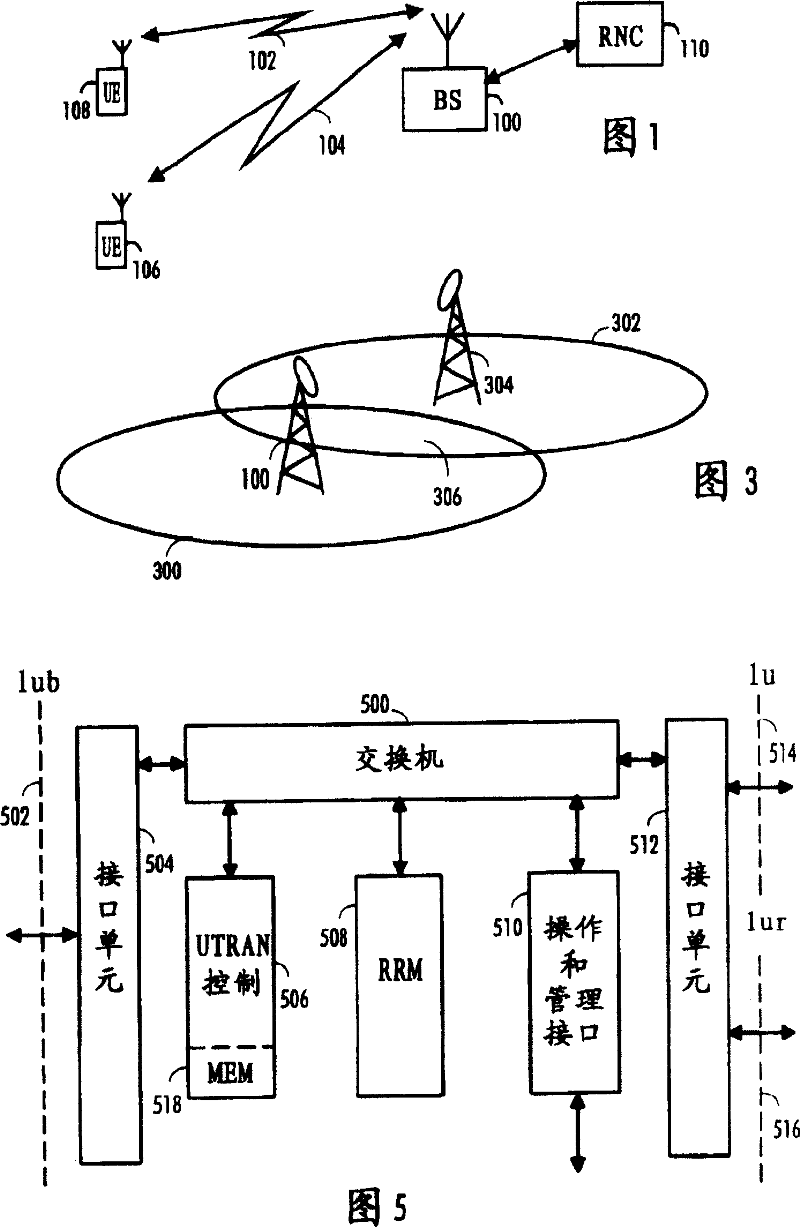
[0017] Fig. 1 shows an example of a data transmission system to which the preferred embodiment of the present invention can be applied. The present invention can be applied to various wireless communication systems. The UMTS (Universal Mobile Telecommunications System) radio access network is an example of such a communication system. It is a wireless access network that includes WCDMA (Wideband Code Division Multiple Access) technology, and can also provide real-time IP (Internet Protocol)-based services, such as IP Telephony (IPT), based on Streaming over IP and multimedia over IP. Those skilled in the art understand that the method according to the present invention can be applied to systems using different modulation methods or different air interface standards.

[0018] Fig. 1 schematically illustrates a digital data transmission system to which embodiments according to the present invention can be applied. As shown in the example of FIG. 1 , this is part of a cellular...


PUM


Abstract

According to one embodiment of the invention, an antenna adjustment method, system and network element is provided. The system includes a mechanism for gathering information on interference in predetermined radio cells, a mechanism for arranging the gathered information radio cell-specifically for processing, a mechanism for determining a tilting factor for each predetermined radio cell, wherein the tilting factor relates to the interference the radio cell produces to other cells, and a mechanism for searching for the radio cells having the antenna tilting factors that fulfill a set criteria.

Description

technical field [0001] The invention relates to an antenna adjustment method, system and network unit of a communication system. Background technique [0002] In a Code Division Multiple Access (CDMA) network where all cells share the same frequency, planning of cell service areas is crucial. If the frequency band overlap of two CDMA cells increases, the quality degradation caused by interference will also increase, because the processing gain will not completely eliminate the interference effect. The size of the wireless cell can only be changed by changing the transmission power or the antenna configuration (antenna tilt or antenna orientation) without changing the hardware. Changing power potentially requires a reset of the base station, which means clearing the cell of traffic. In UMTS (Universal Mobile Telecommunications System), a base station is also called Node B. Furthermore, reducing cell power reduces received power across the entire cell area, not just the cel...

Claims


Application Information

Patent Timeline
Patent Type & Authority Patents(China)
IPC IPC(8): H04Q7/36H04Q7/34H04M3/18H04W16/24H04W16/28H04W24/00
CPCH04W16/28H04W24/00H04M3/18H04W16/24H04M2207/18
Inventor 安蒂·库尔尼艾利·哈玛雷宁艾奇姆·韦克卡里·斯皮拉
Owner NOKIA SOLUTIONS AND NETWORKS SYSTEM TECHNOLOGY (BEIJING) CO LTD
Why Eureka
Try Eureka