Supercharge Your Innovation With Domain-Expert AI Agents!

Oscillator using guide circuit to increase responding speed

An oscillator and drive circuit technology, applied in power oscillators, electrical components, automatic control of power, etc., can solve the problem of high steady state level, increase between high and low steady state levels, transistor T7 drain voltage rise, etc. problem, to achieve the effect of reducing the delay time, reducing the delay time, and correcting the bias voltage

Active Publication Date: 2007-12-19
UNITED MICROELECTRONICS CORP
View PDF4 Cites 0 Cited by
  • Summary
  • Abstract
  • Description
  • Claims
  • Application Information

AI Technical Summary

Problems solved by technology

However, as mentioned earlier, increasing the first control current I p1 The size of the first load transistor T3 will also be biased to a higher cross-voltage, so that the high steady-state level of the negative output terminal OP- output becomes higher; similarly, increasing the second control current I p2 The magnitude of will also cause the high steady-state level of the positive output terminal OP+ output to become higher
In this way, the voltage difference D between the high and low steady-state levels will be increased instead. v , so that the delay time cannot be effectively reduced
In addition, when the output of the negative output terminal OP- is at a high steady-state level, the drain voltage of the transistor T7 will also increase.
If the voltage of the high steady-state level increases, the voltage difference between the gate and the drain of the transistor T7 may be too small, causing the transistor T7 to be biased to the triode region and unable to normally generate the first control current , and make the entire delay unit unable to operate normally

Method used


Image

  • Oscillator using guide circuit to increase responding speed
  • Oscillator using guide circuit to increase responding speed
  • Oscillator using guide circuit to increase responding speed

Examples


Embodiment Construction

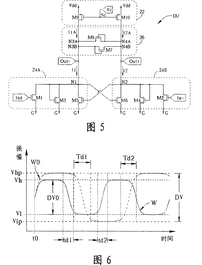
[0042]Please refer to Figure 4. FIG. 4 is a schematic circuit diagram of the ring oscillator 20 of the present invention. Similar to the typical ring oscillator 10 in FIG. 1 , the oscillator 20 is provided with a plurality of delay units DU (three are represented in FIG. 4 ). Each delay unit DU has a positive input terminal In+, a negative input terminal In−, a positive output terminal Out+, a negative output terminal Out− and a frequency control terminal Nc. The positive and negative input terminals In+ and In- are used to input two mutually inverting input signals, and the negative and positive output terminals Out- and Out+ are used to output the inverse input signals of the positive and negative input terminals In+ and In- respectively. output signal. The delay units DU are connected in series, and the positive and negative output terminals Out+ and Out- of each delay unit DU are respectively connected to the negative and positive input terminals In- and In+ of the next ...


PUM


Abstract

An oscillator contains multiple delay units serial mutually, the positive, negative output of each is connected with positive negative input end of another delay unit to generate time pulse, each includes a first drive circuit set with a positive / negative output and a first control end outputting a signal inversing to that of the positive input end by the negative output end, which signal position is controlled by current input by the said first control end, a negative, positive output end and a second driving circuit of the second control end, its positive output outputs a signal inversing to the negative input signal, the position of which is controlled by current input by the second control terminal and a diversion circuit redistributing current supply.

Description

technical field [0001] The present invention provides a ring oscillator (Ring Oscillator) composed of a plurality of delay units, especially an oscillator with a current guiding circuit in the delay unit to speed up the operation. Background technique [0002] In the modern information society, the digital system used to process digital data must use the clock to system 1. Coordinate the timing process of digital data transmission and processing, so the oscillator used to generate the clock has become the most important in modern digital circuits. One of the important basic circuits. In addition, in the signal processing circuits of general communication systems, optical disc drives, hard disk drives, etc., voltage-controlled oscillators (Voltage-Controlled Oscillator, VCO) are often used in their phase lock loops, so as to use The voltage is used to control the period and frequency of the clock pulse generated by the voltage-controlled oscillator. With the acceleration of...

Claims


Application Information

Patent Timeline
Patent Type & Authority Patents(China)
IPC IPC(8): H03B5/26H03L7/08
Inventor 林忠明
Owner UNITED MICROELECTRONICS CORP
Features
  • R&D
  • Intellectual Property
  • Life Sciences
  • Materials
  • Tech Scout
  • Unparalleled Data Quality
  • Higher Quality Content
  • 60% Fewer Hallucinations
Learn More