Method for detecting position and speed of object moving along orbit

A technology for moving objects and detection methods, applied in the direction of speed/acceleration/shock measurement, measurement devices, optical devices, etc., can solve the problems of huge equipment, high cost, and failure to work, and achieve strong anti-electromagnetic interference ability and reliable detection , easy-to-achieve effects

Inactive Publication Date: 2007-12-26
NAT UNIV OF DEFENSE TECH
View PDF6 Cites 0 Cited by
  • Summary
  • Abstract
  • Description
  • Claims
  • Application Information

AI Technical Summary

Problems solved by technology

The odometer is a mechanical positioning measurement device for traditional wheeled vehicles. It uses a principle similar to a mechanical clock to accumulate vehicle displacement. This method has cumulative errors and is greatly affected by weather and terrain. It is only suitable for the positioning and speed measurement of ground wheel-rail vehicles.
Radar is mainly used for early warning, navigation, positioning and detection. Military radar has a detection range of hundreds or even thousands of kilometers and can track hundreds of targets at the same time, but the equipment is huge, the technology is complex, and the cost is high; Traffic management can measure the speed of a designated target, but the effective measurement range of this instrument is small, usually less than 100 meters
GPS is a satellite positioning system established for the U.S. military to provide precise positioning. Military GPS positioning accuracy can reach 1 meter. It is mainly used to determine and track the coordinates of soldiers and equipment traveling in the field, and provide position and Navigation information, etc.; civilian GPS positioning accuracy is about 10 meters, mainly used in surveying and mapping, aviation, navigation, vehicle tracking systems, mobile computers and cellular phone platforms, etc.; GPS network covers the world, and the working conditions are less affected by weather and terrain. Suitable for positioning and speed measurement applications of ground traffic under various open-air conditions; GPS requires that the positioning point be covered by at least 4 satellite signals, so it cannot work in environments such as underground and tunnels

Method used


Image

  • Method for detecting position and speed of object moving along orbit
  • Method for detecting position and speed of object moving along orbit
  • Method for detecting position and speed of object moving along orbit

Examples


Embodiment Construction

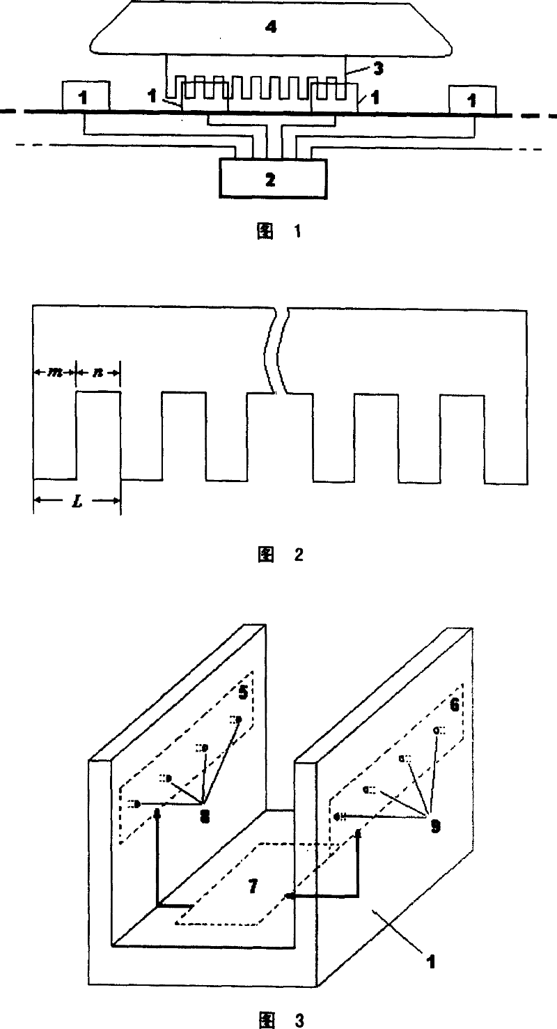
[0043] Fig. 1 is a schematic structural diagram of the positioning and speed measuring system when Embodiment 1 is adopted in the present invention. The positioning and speed measurement system is composed of three parts: the alveolar plate 3 , the partition detector 1 and the upper processor 2 . The alveolar plate 3 is a passive light-blocking device made of dark opaque material. The alveolar plate has a rectangular alveolar shape, all tooth widths are equal, and all slot widths are also equal. The tooth width and the slot width can be taken as equal , can also be taken as unequal. The alveolar plate 3 is installed on the object 4 moving along the track, and the partition detector 1 is installed on the track. The upper processor 2 is generally installed on the ground. All partition detectors 1 are connected with upper processor 2 through cables.

[0044] Fig. 2 is the shape of the alveolar plate of the present invention, the tooth width m and the slot width n constitute a ...


PUM


Abstract

The invention discloses a method for detecting position and velocity of objects moving along track. The inventive method comprises: designing a positioning rate measurement system which comprises a gullet board, a plurality of partition detectors and a processor. The positioning rate measurement system can also comprises a gullet board and partition detectors. When the gullet board, a passive light blocking device, moves relatively to the partition detector, the partition detector calculates vehicle relative movement according to the changing times of positioning status and judges the moving direction of objects according to the shift sequence of positioning status in circular table. The processor combines all the signals detected by partition detectors and calculates the position and velocity of moving objects.

Description

technical field [0001] The invention relates to a method for detecting the position and speed of a moving object, in particular to a method for detecting the position and speed of a moving object such as a vehicle along a track on the ground. Background technique [0002] The positioning and speed measurement system is an important part of the rail vehicle operation control system, and a lot of research has been done at home and abroad. Commonly used positioning and speed measuring devices include odometer, radar and GPS. The odometer is a mechanical positioning measurement device for traditional wheeled vehicles. It uses a principle similar to a mechanical clock to accumulate vehicle displacement. This method has cumulative errors and is greatly affected by weather and terrain. It is only suitable for the positioning and speed measurement of ground wheel-rail vehicles. Radar is mainly used for early warning, navigation, positioning and detection. Military radar has a detec...

Claims


Application Information

Patent Timeline
Patent Type & Authority Patents(China)
IPC IPC(8): G01D5/36G01S17/58G01S17/50G01P13/00G01B11/02
Inventor 李云钢龙志强王宁张鼎张晓
Owner NAT UNIV OF DEFENSE TECH
Why Eureka
Try Eureka