

Automatic bionic transplanting machine
A rice transplanter and automatic technology, which is applied in the field of automatic bionic rice transplanters, can solve the problems of insufficient seedling insertion depth, reduced labor intensity, small transmission resistance, etc., and achieves the effects of good rice transplanting effect, improved survival rate and high survival rate.
- Summary
- Abstract
- Description
- Claims
- Application Information
AI Technical Summary
Problems solved by technology
Method used
Image

Examples
Embodiment 1
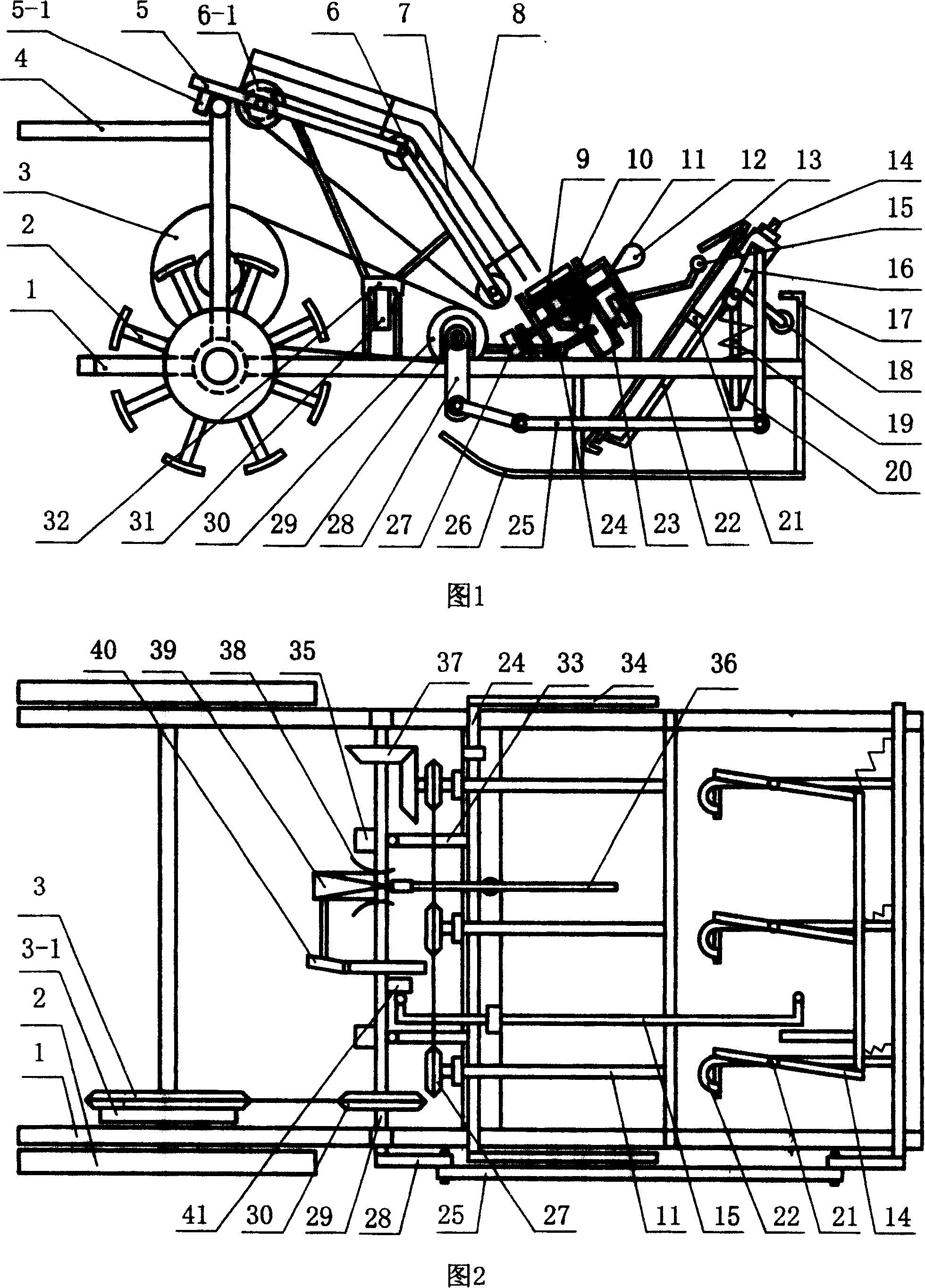
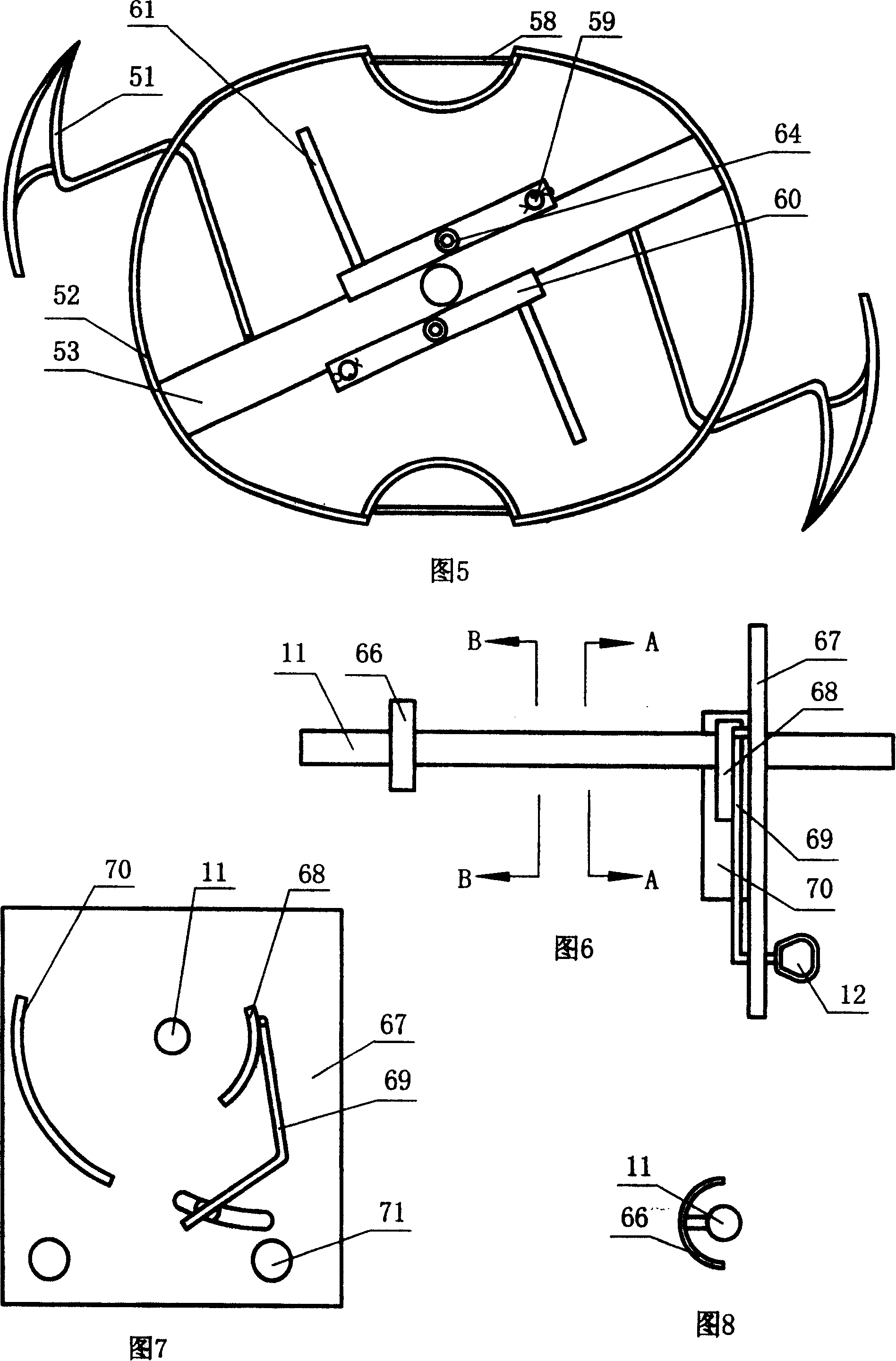
[0029] Embodiment 1: Referring to Fig. 1 to Fig. 8, among the figures, the frame of the automatic bionic rice transplanter includes a horizontal frame 1, and a vertical stand is fixed at the rear of the horizontal frame 1, and a push-pull rod 4 is installed on the vertical stand , the bottom of the horizontal frame 1 rear is equipped with road wheels 2, the bottom of its front is equipped with a boat-shaped bottom plate 26, the driving sprocket 3 is installed on the vertical stand, and is connected with the road wheels 2 through the clutch transmission 3-1. The sprocket 3 is connected with the driven sprocket 30 installed on the horizontal driven shaft 29 in the middle of the horizontal frame 1 through a chain; the front part of the horizontal frame 1 is longitudinally equipped with three groups of seedling devices, wherein the rotating shaft 11 of a group of seedling devices The bevel gear set 37 is connected with the transverse driven shaft 29, and the transmission sprocket 2...
Embodiment 2
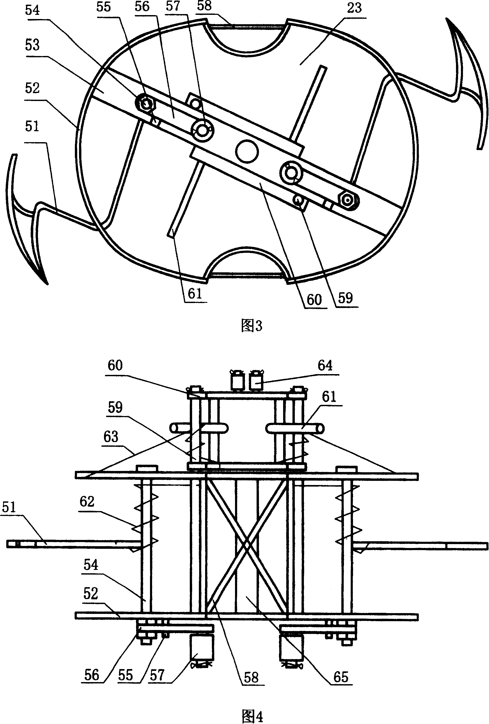
[0033] Embodiment two: this embodiment is basically the same as embodiment one, and the similarities will not be repeated. The difference is that the driving sprocket 3 is connected with the power machine installed on the frame through the clutch speed changer 3-1 to realize mechanical drive separation. Seedling, transplanting, seedling box movement and other processes, saving labor. The fixed support is composed of two elliptical plates and a connecting column between the two plates, and the elliptical plate is a flat plate.
Embodiment 3
[0034] Embodiment three: referring to Fig. 9 and Fig. 10, this embodiment is basically the same as embodiment one, and the similarities will not be repeated. , seedling separating claw, seedling separating frame and root pulling frame, wherein the fixed support is made up of central plate 89 and peripheral plate 90, and central plate 89 is a right-angled trapezoid, and its center is sleeved on the rotating shaft 11, and the inner edge of peripheral plate 90 and The outer edges of the center plate 89 match and have a certain distance to form an annular channel. The center plate 89 and the peripheral plate 90 are respectively connected with the fixed plate 94 of the rotating shaft 11 through the connecting rod 95, and the fixed plate 94 is provided with on it. Mounting hole 92 is fixed on the horizontal frame, keeps stable, and seedling separating claw is one, is made up of the bird's beak shape seedling separating head 82 of the upper end and the curved plate 81 of lower end, fo...
PUM
 Abstract
Description
Claims
Application Information