
Frequency conversion grating rosette production method

A technology of grating strain and manufacturing method, which is applied in the field of optics and can solve problems such as the inability to realize grating manufacturing

Inactive Publication Date: 2008-03-05
SHANGHAI JIAOTONG UNIV
View PDF3 Cites 0 Cited by
  • Summary
  • Abstract
  • Description
  • Claims
  • Application Information

AI Technical Summary

Problems solved by technology

The frequencies of the gratings in the three directions are strictly consistent, and it is impossible to realize the production of gratings with different frequencies in each direction
It is not suitable for situations where there are test sensitivity and measurement range requirements in different directions

Method used


Image

  • Frequency conversion grating rosette production method
  • Frequency conversion grating rosette production method
  • Frequency conversion grating rosette production method

Examples


Embodiment Construction

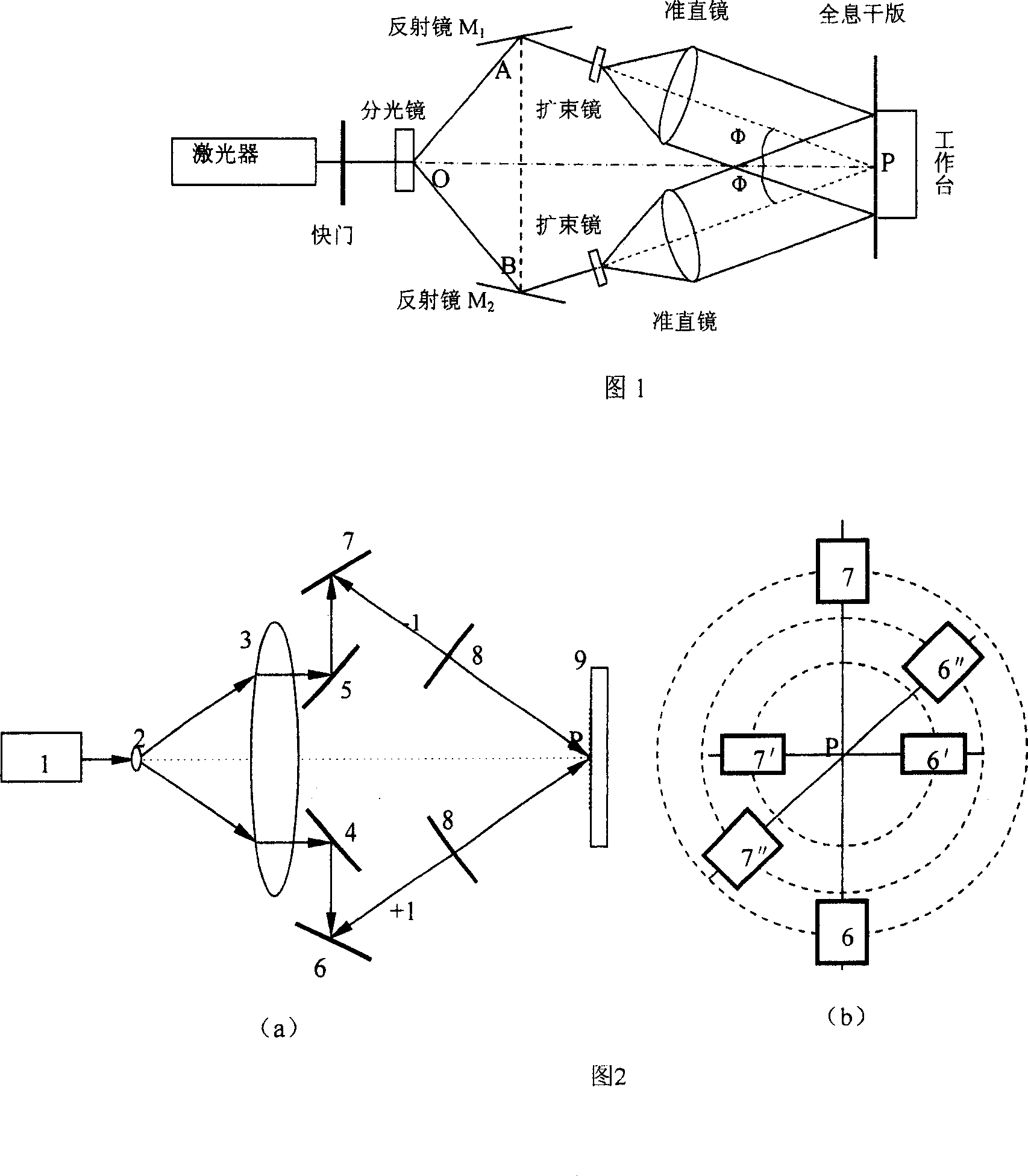
[0018] As shown in Figure 1, each device in Figure 1 is described as follows:

[0019] Laser: wavelength 633×10 -9 m, power 40mW, is a coherent light source;

[0020] Shutter: Control the exposure time;

[0021] Beam splitter: Divide the laser light emitted by the laser into two beams of equal intensity;

[0022] Mirror M 1 , M 2 : change the direction of light propagation;

[0023] Beam expander: 40×, to expand the laser light of the point source and become a spherical wave propagation;

[0024] Spatial filter: 15μm, to filter out the noise existing in the expanded laser;

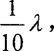
[0025] Collimating mirror: diameter 200mm, phase difference less than 1 10 λ , Collimate the spherical wave from the beam expander to obtain a uniform plane wave front;

[0026] Holographic dry plate: record interference fringes;

[0027] Workbench: Fix the holographic dry plate and change the exposure direction of the holographic dry ...


PUM


Abstract

Wherein, according to frequency of the grating strain rosette on three directions and used laser wavelength, calculating opposite angles; splitting beam from laser into six-beam three-couple coherent light past a beam-expand mirror, a alignment mirror and six reflection mirrors; arranging a reflecting mirror on every light path equally to focus six beams on platform center; selecting beam-expand mirror, a space filter and an alignment mirror to obtain even plane wave front; determining the optimal exposure time for holographic grating; arranging light paths according to former angles, setting the holographic dry plate on platform; exposing, developing, fixing, and obtaining the target. This invention is simple but can obtain diffraction strength on different directions.

Description

technical field [0001] The invention relates to a method in the field of optical technology, in particular to a method for manufacturing grating rosettes with different frequencies in various directions. Background technique [0002] There are two main types of diffraction gratings: ruled gratings and holographic gratings. Ruled gratings can be made into flat or concave shapes, and have high diffraction efficiency for specific light waves. Holographic gratings are generally made by optical methods, and its diffracted waves have very good polarization states and very good wavefronts. The frequency of the grating determines its test resolution. Resolution and measurement range are usually contradictory. For gratings, the higher the frequency, the higher the resolution, but the smaller the measurement range; the lower the frequency, the lower the resolution, but the larger the measurement range. For a grating with the same frequency in all directions, when it is applied in mo...

Claims


Application Information

Patent Timeline
Patent Type & Authority Patents(China)
IPC IPC(8): G02B5/18
Inventor 陈巨兵林卓英俞忠陈玉坤汪恒挥
Owner SHANGHAI JIAOTONG UNIV
Learn More