Check patentability & draft patents in minutes with Patsnap Eureka AI!

Optical fiber sensor

An optical fiber sensor and optical fiber technology, which is applied in the direction of transmitting sensing components, optics, instruments, etc. by using optical devices, can solve the problems that optical fiber sensors cannot measure multiple environmental parameters and high cost, and achieve low cost, low insertion loss, and simplified structure Effect

Active Publication Date: 2008-04-09
GUANGXUN SCI & TECH WUHAN
View PDF7 Cites 0 Cited by
  • Summary
  • Abstract
  • Description
  • Claims
  • Application Information

AI Technical Summary

Problems solved by technology

[0006] The purpose of the present invention is to overcome the problems that traditional optical fiber sensors cannot measure multiple environmental parameters and the cost is high, and propose an optical fiber sensor with low cost, simple structure, and the ability to measure multiple environmental parameters.

Method used


Image

  • Optical fiber sensor
  • Optical fiber sensor
  • Optical fiber sensor

Examples


Embodiment Construction

[0031] Further description will be given below in conjunction with the accompanying drawings and embodiments.

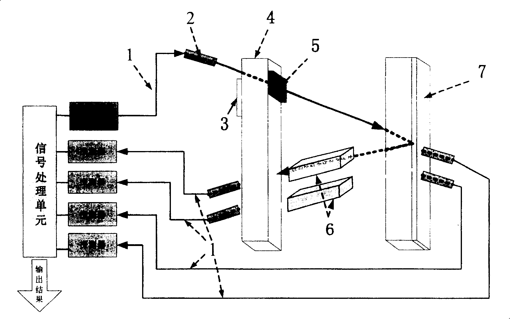
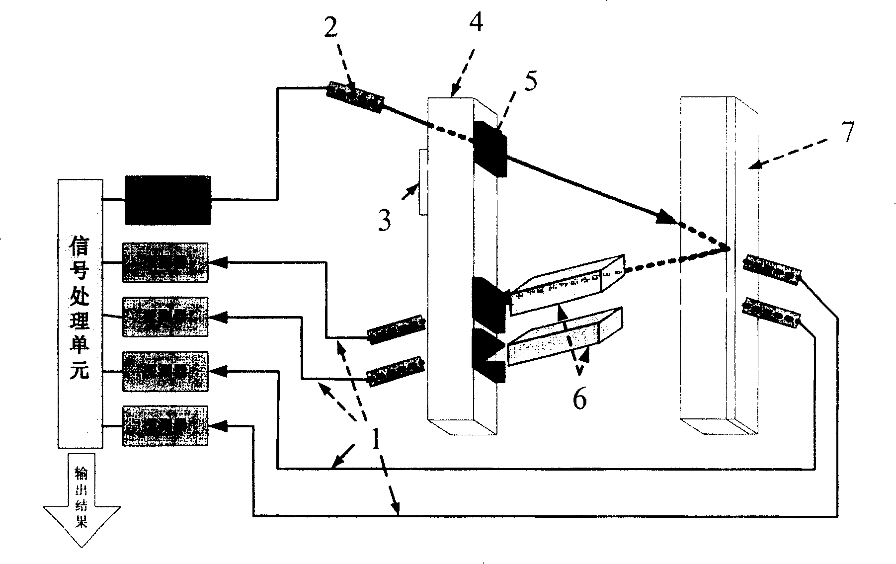
[0032] Such as figure 2 As shown, the infrared laser light coming out of the laser passes through the collimating lens, propagates without loss in the transparent glass 4, and enters the nano-grating polarization beam splitter 5, and is divided into two beams of polarized light whose polarization directions are perpendicular to each other, one of which is polarized The light is reflected, is reflected back by the total reflection mirror 3, and travels together with another beam of polarized light to the transparent glass 4 and the 95% reflector assembly 7, and then enters into different sensitive materials 6 respectively. Since changes in different environmental parameters cause different phase changes, if two beams of polarized light enter two sensitive materials respectively, the phase (intensity, polarization state, etc.) changes caused by multiple environmental p...


PUM


Abstract

The invention relates to a optical fiber sensor, mainly using nanometer grating polarization beam splitter to divide incident light into two bundles of linearly polarized light with vertical polarization direction and they reach a reflecting mirror of uses two probe units to receive light with 5% light intensity as reference light, two bundles of linearly polarized light inflected back go through two blocks of different sensitive material to response one or several environmental parameters. Compared with traditional sensitive material, the structure can separately the advantage of polarization type having high sensitivity to environmental parameter, but also clearer analysis to reference light choice and environment change. The invention needn't to use polarization optical fiber so its resistance to antijamming is excellent and has advantages of small volume, simple structure and low cost.

Description

technical field [0001] The invention relates to an optical fiber sensor, in particular to a method and equipment for splitting beams by using a nanometer grating polarization beam splitter to measure multiple environmental parameters. Background technique [0002] With the development and maturity of dense wavelength division multiplexing technology, erbium-doped fiber amplifier technology and optical time division multiplexing technology, optical fiber communication technology is developing in the direction of ultra-high speed and large capacity, and is gradually evolving into an all-optical network. Driven by the rapid development of the optical communication industry, research on optical fiber sensors has become a hot application field. As a young member of the sensor family, compared with traditional electromechanical sensing systems, it provides an excellent means for environmental monitoring of industrial production processes due to its excellent advantages such as ele...

Claims


Application Information

Patent Timeline
Patent Type & Authority Patents(China)
IPC IPC(8): G01D5/353G02B6/26G02B5/12G02B27/10
Inventor 刘文刘青周立兵杨涛
Owner GUANGXUN SCI & TECH WUHAN
Features
  • R&D
  • Intellectual Property
  • Life Sciences
  • Materials
  • Tech Scout
  • Unparalleled Data Quality
  • Higher Quality Content
  • 60% Fewer Hallucinations
Learn More