Dynamic detector interlacing for computed tomography

A computer and detector technology, applied in the field of computed tomography, can solve the problems of reducing signal-to-noise ratio, increasing cost, complexity bandwidth, etc., to achieve the effect of increasing dynamic range, reducing the number and processing channels, and reducing complexity and cost

Inactive Publication Date: 2008-04-23
KONINKLIJKE PHILIPS ELECTRONICS NV
View PDF4 Cites 2 Cited by
  • Summary
  • Abstract
  • Description
  • Claims
  • Application Information

AI Technical Summary

Problems solved by technology

However, these approaches increase the cost, complexity, and bandwidth of the data acquisition system and associated signal processing electronics
These methods also reduce the signal-to-noise ratio by reducing the acquisition time or detector area respectively

Method used


Image

  • Dynamic detector interlacing for computed tomography
  • Dynamic detector interlacing for computed tomography
  • Dynamic detector interlacing for computed tomography

Examples


Embodiment Construction

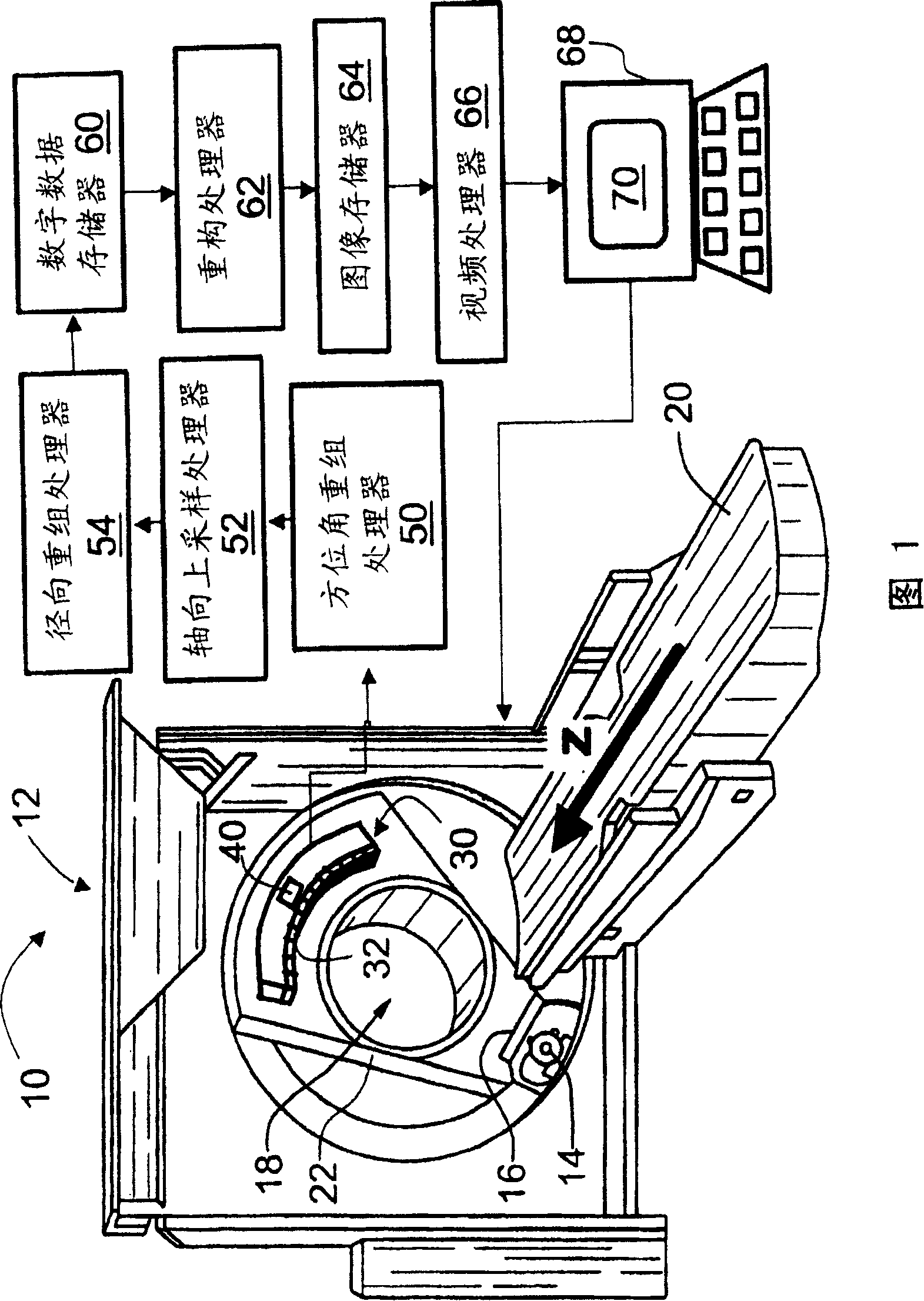
[0025] Referring to FIG. 1 , a computed tomography (CT) imaging apparatus 10 includes a CT scanner 12 having an x-ray source 14 and a collimator 16 that together generate a cone, wedge, or other shaped beam of x-rays that impinges into an examination region 18 . A subject (not shown), such as a patient, is placed on the subject carrier 20 and placed at least partially in the examination region 18 . Preferably, the patient body 20 is movable linearly in the axial or Z direction, while the X-ray source 14 is rotatable on a rotating gantry 22 .

[0026] In an exemplary helical imaging mode, gantry 22 rotates while subject body 20 advances linearly and axially to create a helical trajectory of x-ray source 14 and collimator 16 around examination region 18 . However, other imaging modes may also be used, such as a multi-slice imaging mode in which the gantry 22 is rotated while the subject body 20 remains stationary to create a circular trajectory of the X-ray source 14 to acquire...


PUM


Abstract

A data acquisition system (DAS) ( 30 ) for a computed tomography (CT) scanner ( 12 ) includes a two-dimensional array ( 32 ) of detectors ( 34 ) which is arranged to detect x-rays produced by the CT scanner ( 12 ). Each detector ( 34 ) is divided into two sub-detectors ( 34 a, 34 b) along an axial direction (z). A high-speed switching circuit ( 40 ) combines selected adjacent sub-detector outputs ( 34 a, 34 b), e.g. combining a sub-detector n alternately with sub-detectors (n- 1 ) and (n+ 1 ). The high-speed switching circuit ( 40 ) switches its configuration between DAS measurements to produce interlaced DAS output signals along the axial direction (z).

Description

technical field [0001] The present invention relates to diagnostic imaging techniques. It particularly relates to computed tomography using two-dimensional detector arrays, which enables rapid acquisition of volumetric imaging data, and will be described with reference to specific references. However, the present invention finds application with other types of detector arrays for various imaging applications employing x-ray, visible light, or other types of radiation. Background technique [0002] Computed tomography (CT) typically employs an x-ray source that produces a fan-beam or cone-beam of x-rays that penetrate the examination region. Objects placed in the examination area interact with the passing X-rays and partly absorb them. A CT data acquisition system (DAS) including a two-dimensional detector array is positioned opposite the x-ray source to detect and measure the intensity of the transmitted x-rays. Typically, the X-ray source and DAS are mounted on opposite ...

Claims


Application Information

Patent Timeline
Patent Type & Authority Patents(China)
IPC IPC(8): A61B6/03
CPCA61B6/5205A61B6/4021A61B6/4085A61B6/032
Inventor C·J·布伦内特
Owner KONINKLIJKE PHILIPS ELECTRONICS NV
Why Eureka
Try Eureka