Brushless motor Hall position correction method based on Hall sensor

A Hall sensor, Hall position technology, applied in the direction of electronic commutator, monitoring commutation, etc., can solve the problems of large current, sensitivity error, low motor efficiency, etc.

Pending Publication Date: 2021-09-24
深圳市旭顺电子有限公司
View PDF10 Cites 0 Cited by
  • Summary
  • Abstract
  • Description
  • Claims
  • Application Information

AI Technical Summary

Problems solved by technology

[0004] The purpose of the present invention is to provide a Hall sensor-based brushless motor Hall position correction method to solve the problem in the production of three-phase brushless motors with Hall sensors in the above-mentioned background technology. The error of Hall's sensitivity, the deviation of Hall installation, the error of rotor installation and the change of rotor magnetic field, etc., make the magnetic field signal sensed by Hall and the actual magnetic field easy to have a large error, resulting in large current and noise. Low motor efficiency and other phenomena, in order to accurately obtain the rotor speed and position information required by the closed-loop speed and space vector pulse modulation, it is generally necessary to install a high-precision position sensor on the shaft end of the motor rotor, although the introduction of a high-precision position sensor can ensure the motor. Control results, but there are also problems of low system reliability and increased costs

Method used


Image

  • Brushless motor Hall position correction method based on Hall sensor
  • Brushless motor Hall position correction method based on Hall sensor

Examples


Embodiment 1

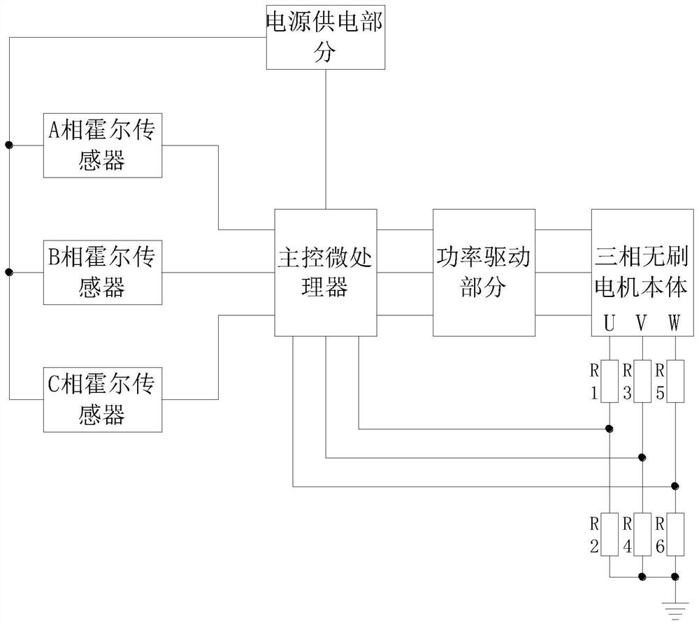
[0031] Step 1: Connect the three-phase brushless motor to the power supply of the motor. After the connection is completed, start the motor. After starting the motor, check whether there is any abnormality in the Hall signal. If there is no abnormality, calculate the Hall electrical angle and check whether the motor is running. The following situations occur: stalling, shaking, reverse rotation, stalling or large fluctuations in speed. If none of the above situations occurs, it is judged that the motor is operating normally, and the Hall electrical angle is determined by the formula Calculate, wherein the value of T1 is 0, and the value of T2 is 30, then it can be obtained that the angle is 180 degrees.

[0032] Step 2: Correct the Hall position of the motor according to the signal collected by the Hall sensor. By connecting a resistor with the same resistance value on the DC bus, two current samples are taken within one pulse width modulation cycle to compensate for the non-o...

Embodiment 2

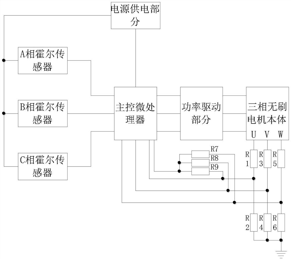
[0036] Step 1: Connect the three-phase brushless motor to the power supply of the motor. After the connection is completed, start the motor. After starting the motor, check whether there is any abnormality in the Hall signal. If there is no abnormality, calculate the Hall electrical angle and check whether the motor is running. The following situations occur: stalling, shaking, reverse rotation, stalling or large fluctuations in speed. If none of the above situations occurs, it is judged that the motor is operating normally, and the Hall electrical angle is determined by the formula Calculate, wherein the value of T1 is 0, and the value of T2 is 20, then it can be obtained that the angle is 120 degrees.

[0037] Step 2: Correct the Hall position of the motor according to the signal collected by the Hall sensor. By connecting a resistor with the same resistance value on the DC bus, two current samples are taken within one pulse width modulation cycle to compensate for the non-o...


PUM


Abstract

The invention discloses a brushless motor Hall position correction method based on a Hall sensor, and the method comprises the steps: adding a three-phase Hall position correction part circuit, employing R1, R2, R3, R4, R5 and R6, carrying out the voltage sampling of a three-phase coil of a motor when the motor starts to operate, directly transmitting a sampled signal to a main control microprocessor, wherein a three-phase signal can reflect a back electromotive force signal of an actual magnetic field position of the motor and a commutation zero point signal, the master control microprocessor calculates the position of the signal sensed by the Hall and the deviation between the position of the signal sensed by the Hall and a signal sampled by the three-phase Hall position correction part according to three paths of sampled voltage signals to obtain a correct position signal, the position of the motor can be corrected by using R1, R2, R3, R4, R5, R6, R7 and R8, sampling of a three-phase zero crossing point is added, four paths of signals after sampling are sent to the master control microprocessor to calculate the deviation between a Hall position and an actual magnetic field position, a corrected position signal is obtained, and the problems of large current, large noise and low motor efficiency are solved.

Description

technical field [0001] The invention relates to the technical field of brushless motors, in particular to a method for correcting the Hall position of a brushless motor based on a Hall sensor. Background technique [0002] The brushless DC motor is composed of the main body of the motor and the driver. It is a typical mechatronics product. Since the brushless DC motor operates in a self-controlled manner, it will not be in the rotor like a synchronous motor that is started under heavy load under variable frequency speed regulation. Adding a starting winding on it will not cause oscillation and out of step when the load changes suddenly. The Hall effect is a kind of electromagnetic effect. When the current passes through the semiconductor perpendicular to the external magnetic field, the carriers are deflected, perpendicular to the current and the magnetic field The direction of the direction will generate an additional electric field, thereby generating a potential differenc...

Claims


Application Information

Patent Timeline
IPC IPC(8): H02P6/16H02P6/12
CPCH02P6/16H02P6/12
Inventor 黄飞
Owner 深圳市旭顺电子有限公司
Why Eureka
Try Eureka