
Material blend crusher

A pulverizing device and material mixing technology, applied in grain processing and other directions, can solve the problems of uneven mixing, high operating cost, long mixing time, etc., and achieve the effect of shortening working time, reducing production cost and improving productivity.

Inactive Publication Date: 2008-05-14
韩飞
View PDF5 Cites 1 Cited by
  • Summary
  • Abstract
  • Description
  • Claims
  • Application Information

AI Technical Summary

Problems solved by technology

The device has the following disadvantages: a. The stirring time is long and the speed is slow; b. It is easy to agglomerate and form a dough; c. The stirring is uneven; d. The condensate is accumulated or adsorbed on the container tank, tank wall or internal joint fittings
This process has the following disadvantages: a. The rotor and stator wear quickly, and usually a set of rotor and stator has to be replaced every six months to one year; b. The processing capacity is small and the speed is slow; c. Loud noise; d. High energy consumption; e .Only suitable for low viscosity, low concentration products
Its disadvantages are: a. It can only be applied to products with low viscosity and low concentration, and it cannot be applied when the concentration and viscosity of the product are high; b. There are often dead corners and residues in the system that are not easy to clean; c. The function is single, No crushing and emulsifying functions; d. Cannot adjust the particle size; e. Small processing capacity, only suitable for small and medium-scale production requirements
This structure is suitable for high-viscosity products, but not for low-viscosity products. At the same time, the processing capacity is small, and it is only suitable for small-scale production requirements; the system is expensive and high in cost; there are many accessories, complicated maintenance, and high operating costs. ; The system has a single function and does not have a crushing function

Method used


Image

  • Material blend crusher
  • Material blend crusher
  • Material blend crusher

Examples


Embodiment Construction

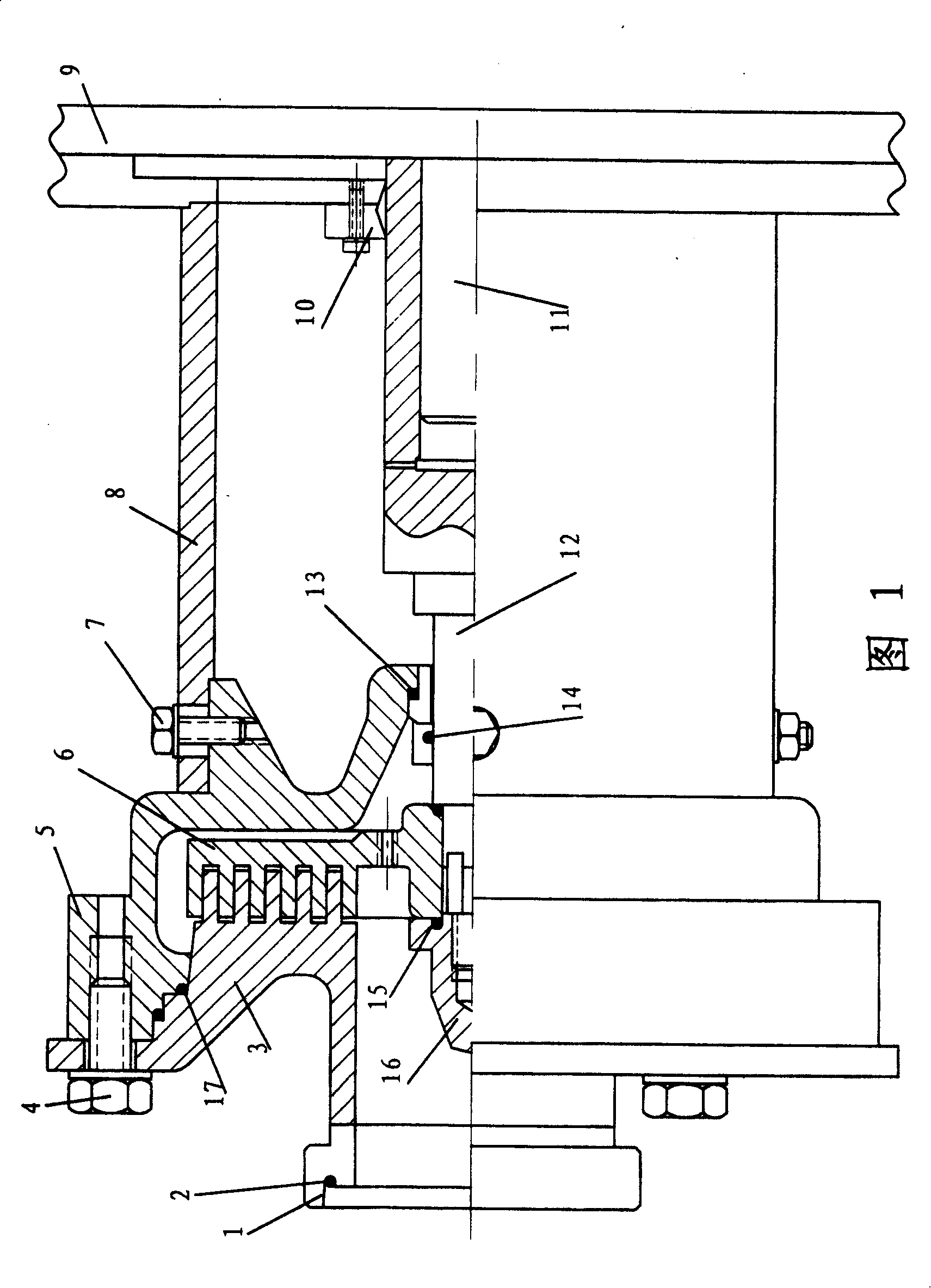
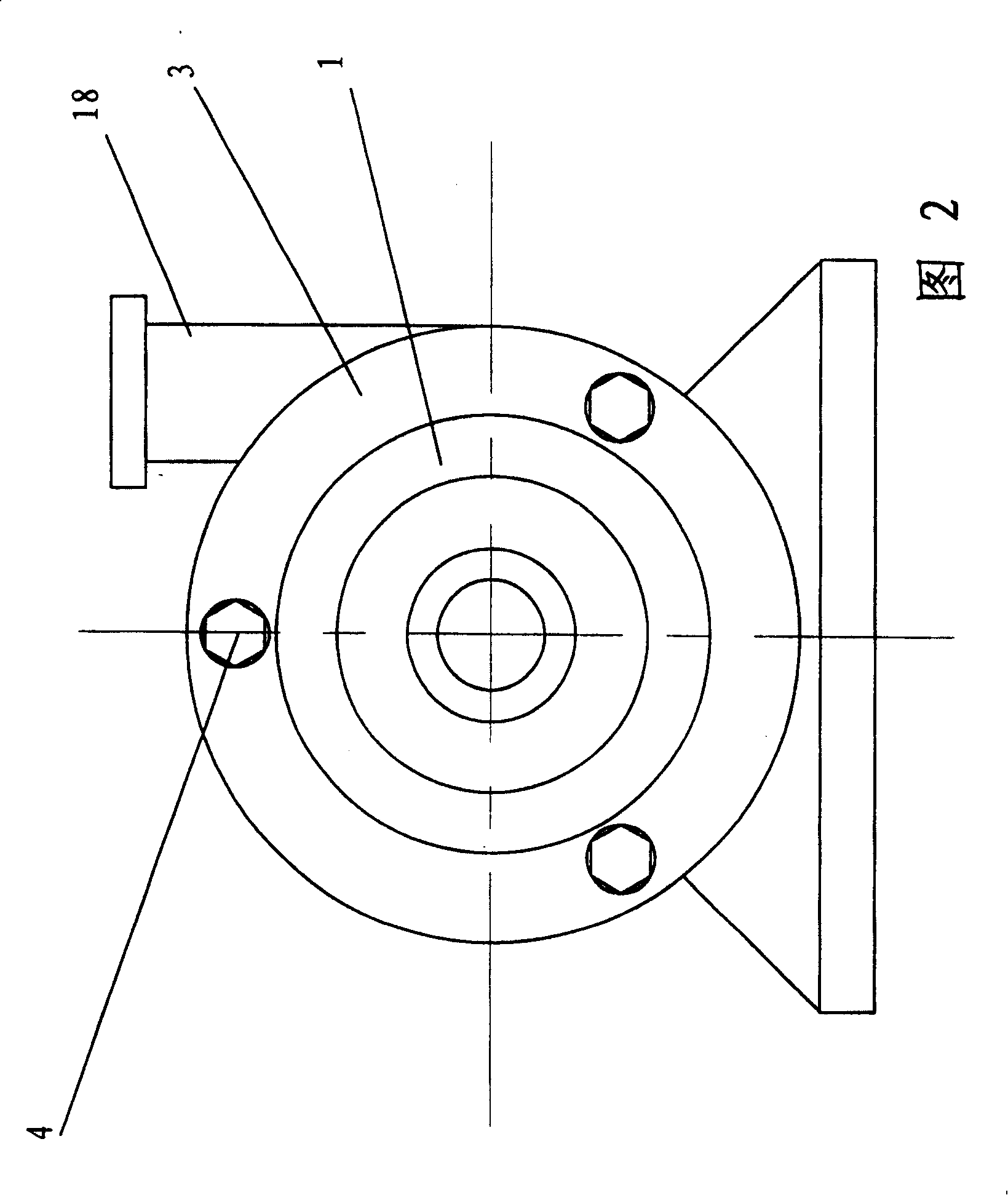
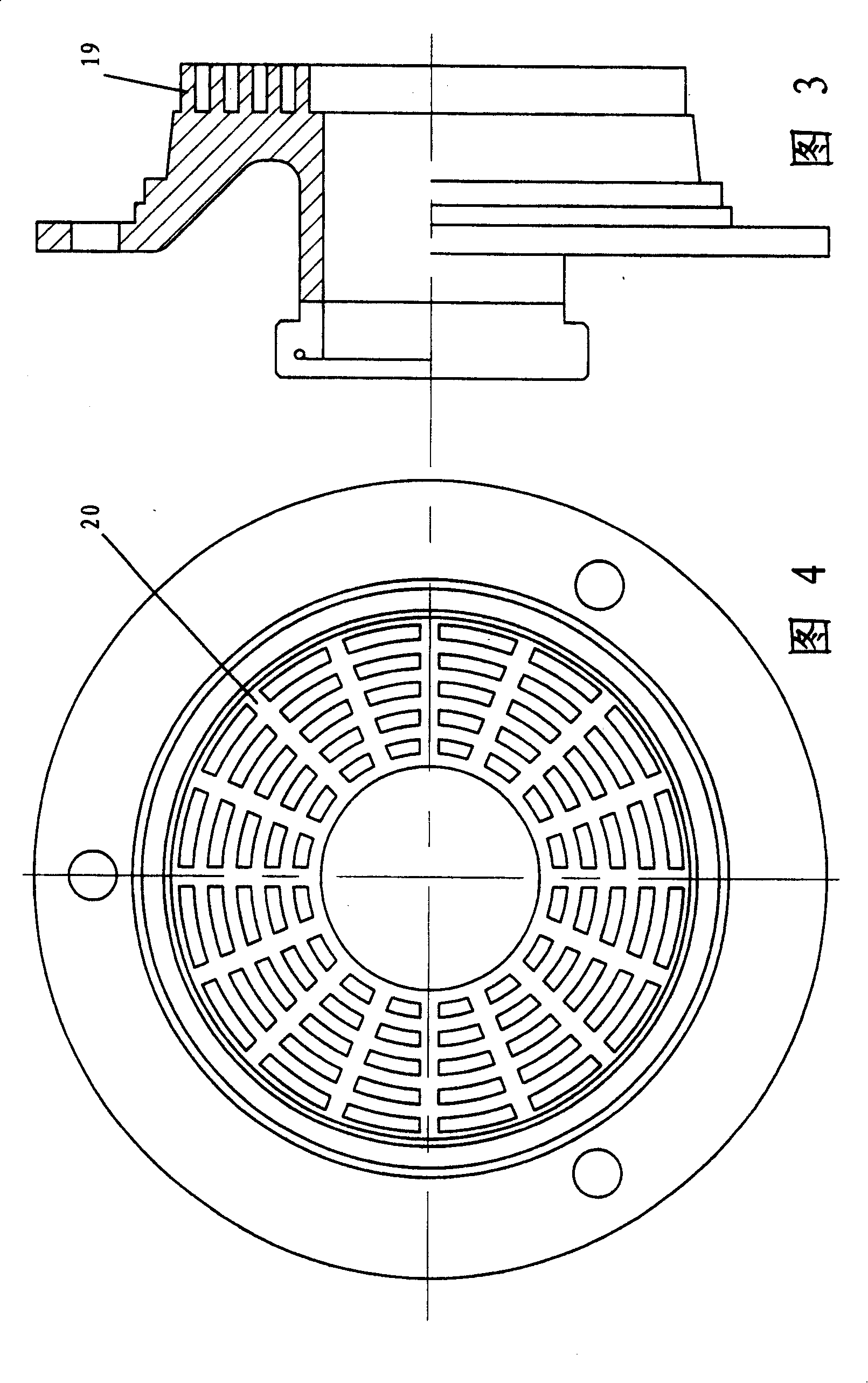
[0029] 1 and 2, the material mixing and pulverizing device according to the present invention includes a cavity 5, a stator 3 fixedly connected with the cavity and having a central feeding port, and a stator 3 fitted with the stator and fixedly mounted on the rotating shaft sleeve 12. Rotor 6. One end of the cavity 5 is connected to the motor flange 9 through the connecting cylinder 8, and its inner hole is mounted on the rotating sleeve 12, which is connected to the motor shaft 11 through a coupling 10 (commercially available).

[0030] The cavity 5 is the main part of the mixing and pulverizing device, and its shape is like a snail shell, with a discharge port on one side of the cavity, the outer surface of the end connected with the connecting cylinder 8 is tightly fitted with the connecting cylinder, and has threaded holes. 3-6. The connecting cylinder 8 has an axially long through hole matched with the threaded hole of the cavity 5 for adjusting the axial gap between the...


PUM


Abstract

The invention relates to a mixed crush device of material, comprising a chamber in the shape of snail shell; a discharging outlet at one side of chamber; a stator connected with chamber with a central feeding inlet; a rotator matched said stator and fixed on the rotational shaft sleeve. Wherein, one end of said chamber is connected to the motor flange disc via connection cylinder, while its inner hole is mounted on the rotational shaft sleeve which is connected to the motor shaft via coupling. The invention integrates the functions of mixing, diffusing, emulsifying and making uniformly, while it can diffuse the group effectively with strong versatility. Compared to traditional big pot or mixing-milling device, it can shorten 90% working time to improve the producing efficiency, and reduce the cost. And said invention can apply the products at any viscosities, with smaller space, simple structure, reliability, easy operation, and lower operation cost.

Description

technical field [0001] The invention relates to material processing equipment, in particular to a material mixing and pulverizing device. Background technique [0002] Over the years, in the fields of food, medicine, chemical industry, etc., the equipment for mixing, stirring, and crushing of materials mainly includes: [0003] 1. Mixing-stirring in large tanks or containers is currently dominant in industrial production practice. The solid raw material is put into a large tank or container together with the liquid raw material and stirred with a stirrer until the coagulum is completely dispersed in the raw material. The time required for this process varies, but at least 40-150 minutes is required depending on the amount of the mixture and the concentration of the thickener. The device has the following disadvantages: a. long stirring time and slow speed; b. easy to agglomerate and form powder mass; c. uneven stirring; When the material is drawn out, these agglomerates w...

Claims


Application Information

Patent Timeline
Patent Type & Authority Patents(China)
IPC IPC(8): B02C2/10B02C19/00
Inventor 韩飞
Owner 韩飞
Learn More