Diaphragm-holding device for test

A technology of diaphragm and testing mechanism, which is applied in the direction of measuring device casing, electronic circuit testing, etc., can solve the problems of increased false detection rate, easy wear and tear of electrical connection film, and inability to fit tightly, so as to improve the false detection rate and save consumable consumption Cost, effect of improving noise pollution

Inactive Publication Date: 2008-05-28
简新锋
View PDF4 Cites 0 Cited by
  • Summary
  • Abstract
  • Description
  • Claims
  • Application Information

AI Technical Summary

Problems solved by technology

[0011] Although the above-mentioned diaphragm pinching device 2 can hold the electronic module 1 for electrical testing, since the clamping unit 22 is driven by the driving cylinder 24 to move, it will not only generate a lot of noise during the action, but also because of the instantaneous pinching The pressure makes the first electrical connection row 232 of the electrical connection film 231 easy to wear and must be replaced frequently
Furthermore, the circuit board 11 of the electronic module 1 will be bent and deformed due to the welding of multiple integrated circuit packages 12, or due to the influence of external temperature and absorption of water vapor, etc., thus causing the two clamping claws 221 to rigidly clamp the electronic module. 1 cannot be closely matched, so that the first electrical connection row 232 of the electrical connection film 231 cannot be electrically connected to the corresponding electrical contact 13 correctly, resulting in an increase in the false detection rate

Method used


Image

  • Diaphragm-holding device for test
  • Diaphragm-holding device for test
  • Diaphragm-holding device for test

Examples


Embodiment Construction

[0036]Before the present invention is described in detail, it should be noted that in the following description, similar elements are denoted by the same reference numerals.

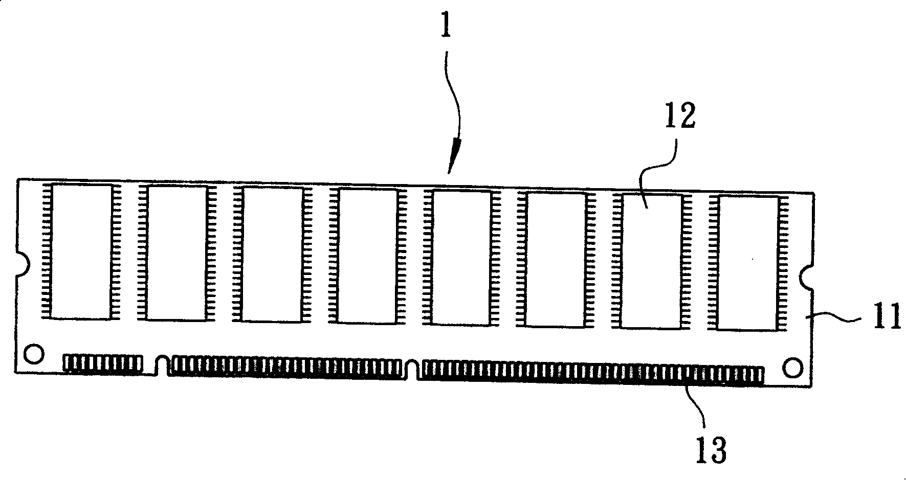
[0037] refer to Image 6 and Figure 7 , a first preferred embodiment of the present invention's testing membrane clamping device 3 is similar to the above-mentioned existing membrane clamping device 2, and is a replaceable holding device such as figure 1 The electronic module 1 shown in the figure further electrically connects the electronic module 1 to a testing mechanism 200 (shown only schematically in the figure) preset with testing software, so as to conduct an electrical test on the electronic module 1 .

[0038] The test diaphragm clamping device 3 includes a fixing base 4 , a clamping piece 5 , an electrical connection unit 6 and an air control unit 7 .

[0039] The fixing base 4 has two opposite fixed pieces 41, the two fixed pieces 41 jointly define a slot 42, and an electrical connection sp...


PUM


Abstract

The present invention relates to a diaphragm -holding device for test. It includes a fixing seat that can changeably clamp electronic module, holding sheet whose form can be elastically changed, electric connection unit and pneumatic control unit that are substitutionally fixed on the holding sheet. Besides, said invention also provides the working principle, and concrete operation method and steps of said diaphragm- holding device.

Description

technical field [0001] The invention relates to a clamping device, in particular to a clamping device for holding an electronic module for electrical testing. Background technique [0002] refer to figure 1 Generally, the electronic module 1 includes a circuit board 11 with a circuit, a plurality of integrated circuit packages 12 (integrated circuit packages) welded to the circuit board 11, and a plurality of integrated circuit packages arranged at intervals on one side of the circuit board 11. Each integrated circuit package 12 is electrically connected to the circuit of the circuit board 11, and each electrical contact 13 is also electrically connected to the circuit of the circuit board 11. The module 1 is electrically connected to another electronic product through a plurality of electrical contacts 13 , so that the electrical connection functions. For example, generally the most common electronic module 1 is a dynamic random access memory (RAM) that can be connected t...

Claims


Application Information

Patent Timeline
Patent Type & Authority Patents(China)
IPC IPC(8): G01R1/04G01R31/28
Inventor 简新锋
Owner 简新锋
Why Eureka
Try Eureka