Catalytic cracking conversion method with relay use of catalyst curd its device

A catalytic cracking and catalyst technology, applied in the petroleum industry, dealing with hydrocarbon oil, etc., can solve the problem that the gasoline reaction is not fully utilized, and achieve the effects of inhibiting the thermal cracking reaction, increasing the ratio of agent to oil, and improving the activity

Inactive Publication Date: 2008-06-11
石宝珍
View PDF9 Cites 0 Cited by
  • Summary
  • Abstract
  • Description
  • Claims
  • Application Information

AI Technical Summary

Problems solved by technology

In the prior art, these characteristics of gasoline reaction have not been fully utilized

Method used


Image

  • Catalytic cracking conversion method with relay use of catalyst curd its device
  • Catalytic cracking conversion method with relay use of catalyst curd its device
  • Catalytic cracking conversion method with relay use of catalyst curd its device

Examples


Embodiment 1

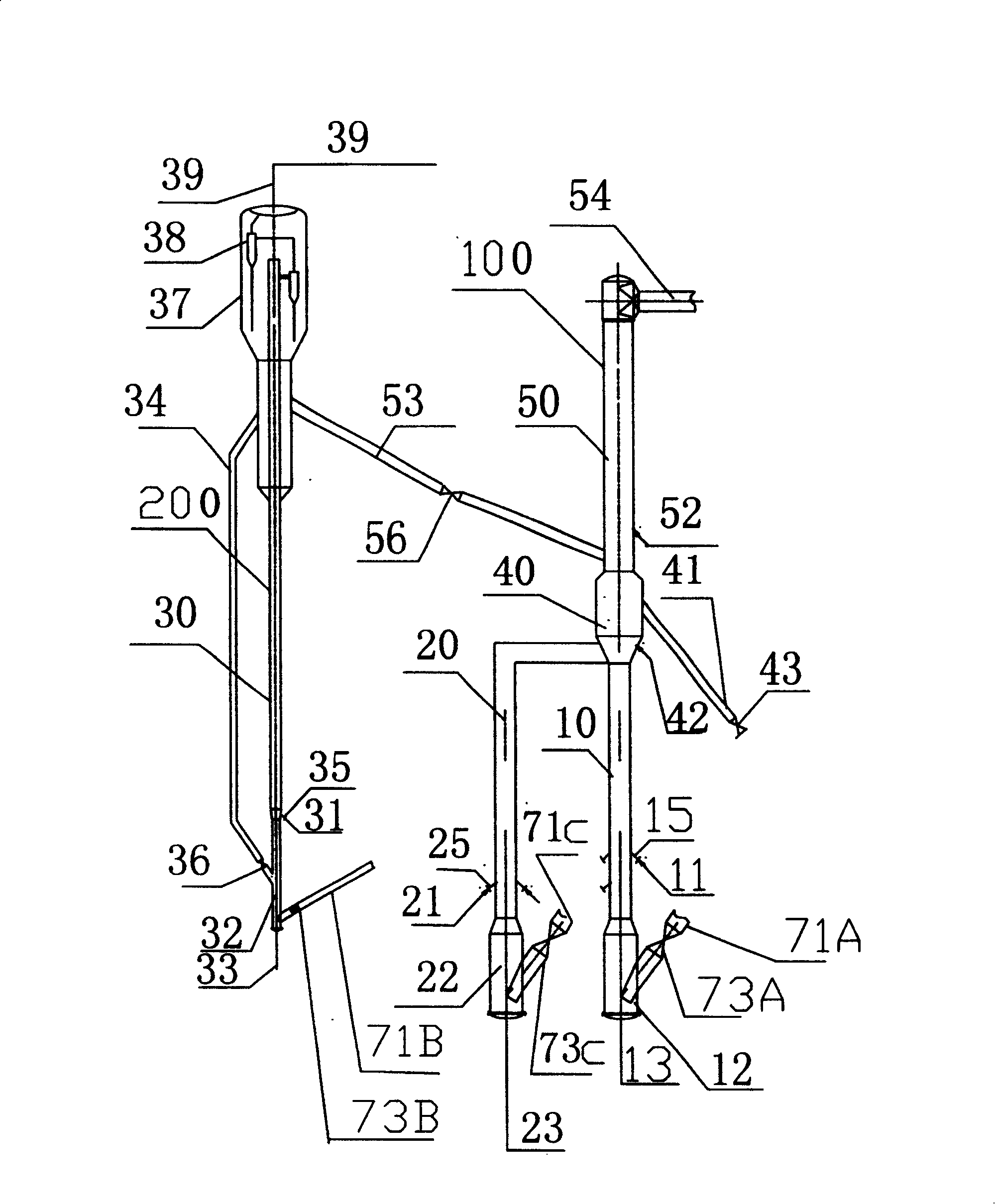
[0034] Embodiment 1, the catalytic cracking conversion unit that catalyst relay uses (see figure 1 ), including a heavy oil reactor 100 and a gasoline reactor 200 arranged in parallel therewith. The heavy oil reactor 100 is composed of a lower cracking reaction section, a middle separation and stripping section 40 and an upper upgrading reaction section 50 in series. The cracking reaction section includes a feedstock oil riser 10 and a re-refined oil riser 20 arranged in parallel, and the re-refined oil The riser 20 is arranged outside the raw oil riser 10, and its upper ends are connected. The separation and stripping section 40 is provided with a catalyst separation and stripping mechanism and a standby catalyst riser 41, 41 is the catalyst stripping medium of the heavy oil cracking reaction section, and 43 is a slide valve to be produced. Technology; upgrading reaction section 50 is in the form of a riser, 54 is the outlet pipe of the heavy oil reactor, and the cooling med...

Embodiment 2

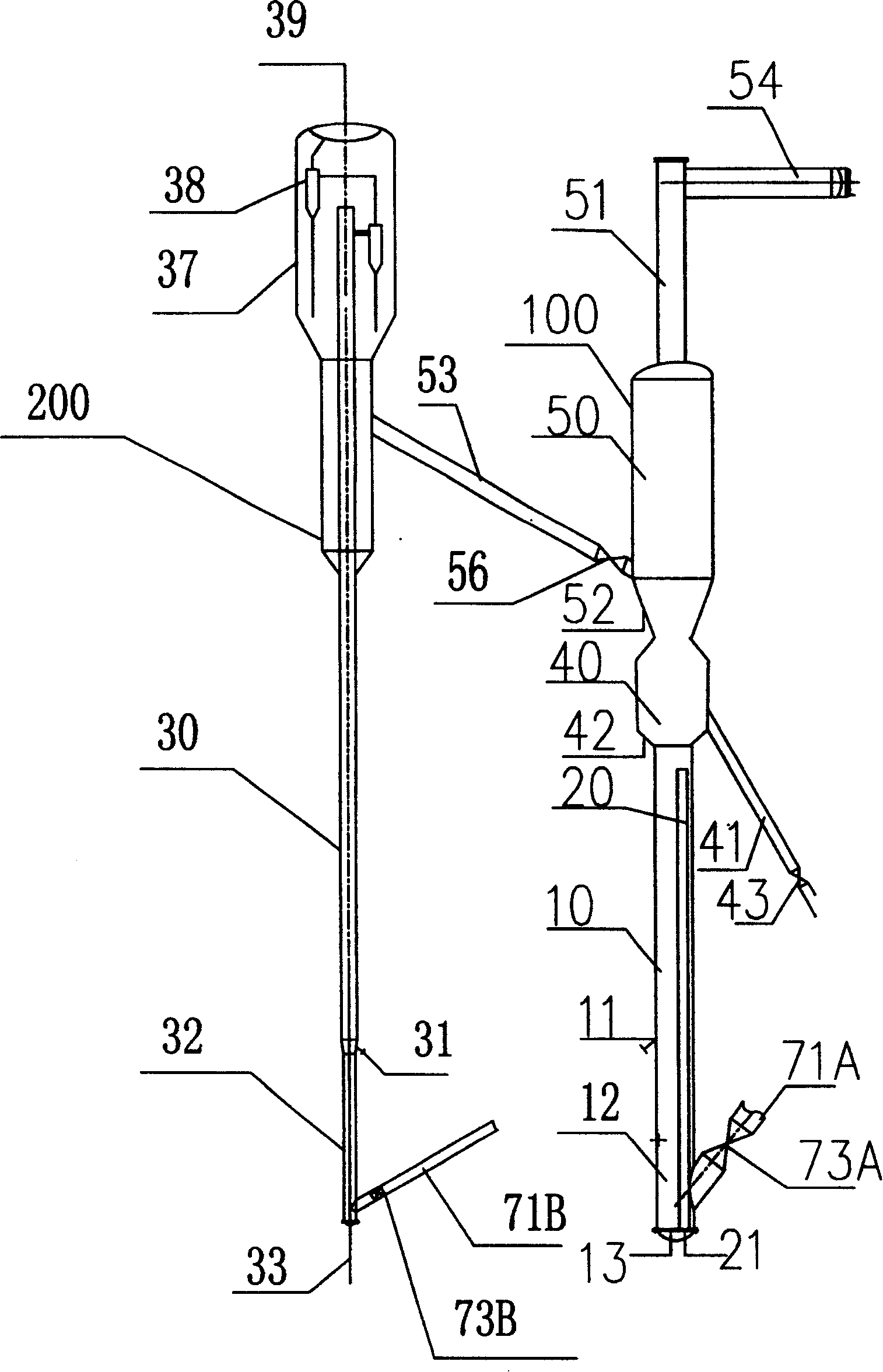
[0044] Embodiment 2. The difference between the device of this embodiment and that of Embodiment 1 is that the recycled oil riser 20 of the heavy oil reactor 100 is sleeved in the raw oil riser 10, and the two have the same axial direction; the recycled oil 21 enters from the bottom of the reactor. The recycled oil riser 20, the raw oil riser 10, and the recycled oil riser 20 share the regeneration standpipe 71A and the slide valve 73A. The upgrading reaction section 50 is in the form of a fluidized bed, and the section 51 is a heavy oil reaction delivery pipe. There is no catalyst return pipe between the gasoline settler 37 and the bottom of the gasoline reactor 200 .

Embodiment 3

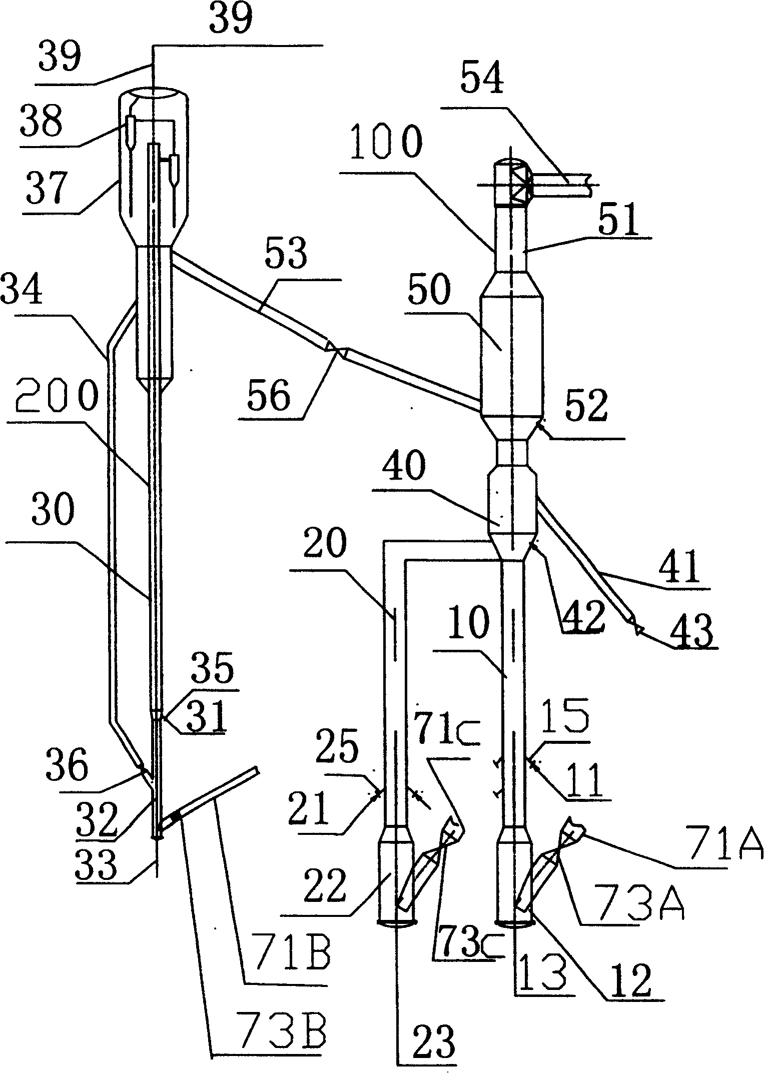
[0045] Embodiment 3. The device of this embodiment is different from that of Embodiment 1 in that: the reforming reaction section 50 is in the form of a fluidized bed, and 51 is a heavy oil reaction delivery pipe.


PUM


Abstract

The invention is a catalyst relay catalytic cracking conversion method and device, belonging to petroleum refining technical field, making raw oil and back-refined oil firstly perform catalytic cracking reaction in the respective risers, successively merging and extracting deactivated catalyst, where the reacting oil gas changes to contact with low temperature catalyst used in the gasoline reaction and continue reaction; a heavy oil reactor is connected in parallel with a gasoline reactor; the gasoline and catalyst complete reaction in the gasoline reactor and then can make gas-solid separation in a gasoline settler, where the oil gas is discharged through pipeline, the extracted catalyst is fed into the position below heavy oil modifying reaction stage and cracking reaction stage to continue heavy oil reaction and can also be fed into a gas-solid separator arranged in the heavy oil modifying reaction stage for separating, where the gasoline gas is directly drawn out and the catalyst takes part in the reaction in this stage; a catalyst return pipe is arranged between the gasoline settler and gasoline reactor bottoms to make a part of catalyst used in the gasoline reaction return to the gasoline reactor bottom so as to take part in the gasoline reaction again.

Description

technical field [0001] The invention belongs to the technical field of petroleum refining, and in particular relates to a catalytic cracking conversion method and a device thereof using catalyst relay. Background technique [0002] Catalytic cracking is the most important processing device for heavy petroleum fractions (including vacuum wax oil, coker wax oil, atmospheric press oil, vacuum press oil, etc.), and is the production device for 80% of gasoline in China. The catalytic cracking reaction uses a riser reactor. The reaction raw materials enter at the bottom of the riser. Under the catalyst environment, the reaction is carried out at an average flow rate of about 15m / s and a temperature of about 500°C. The reaction time is generally about 3s, and the length of the riser is 30-40 meters. During the reaction process, about 7-10% of the raw materials will be converted into coke, which will adhere to the surface and pores of the catalyst, deactivate the catalyst and lose ...

Claims


Application Information

Patent Timeline
Patent Type & Authority Patents(China)
IPC IPC(8): C10G57/00
Inventor 石宝珍
Owner 石宝珍
Why Eureka
Try Eureka