Cross coil instrument with a predefined characteristic

A cross-coil and instrument technology, applied in the field of cross-coil instruments

Inactive Publication Date: 2008-06-11
戴夫
View PDF6 Cites 1 Cited by
  • Summary
  • Abstract
  • Description
  • Claims
  • Application Information

AI Technical Summary

Problems solved by technology

There is currently no easy way to alter the characteristics of known cross-coil gauges

Method used


Image

  • Cross coil instrument with a predefined characteristic
  • Cross coil instrument with a predefined characteristic
  • Cross coil instrument with a predefined characteristic

Examples


Embodiment Construction

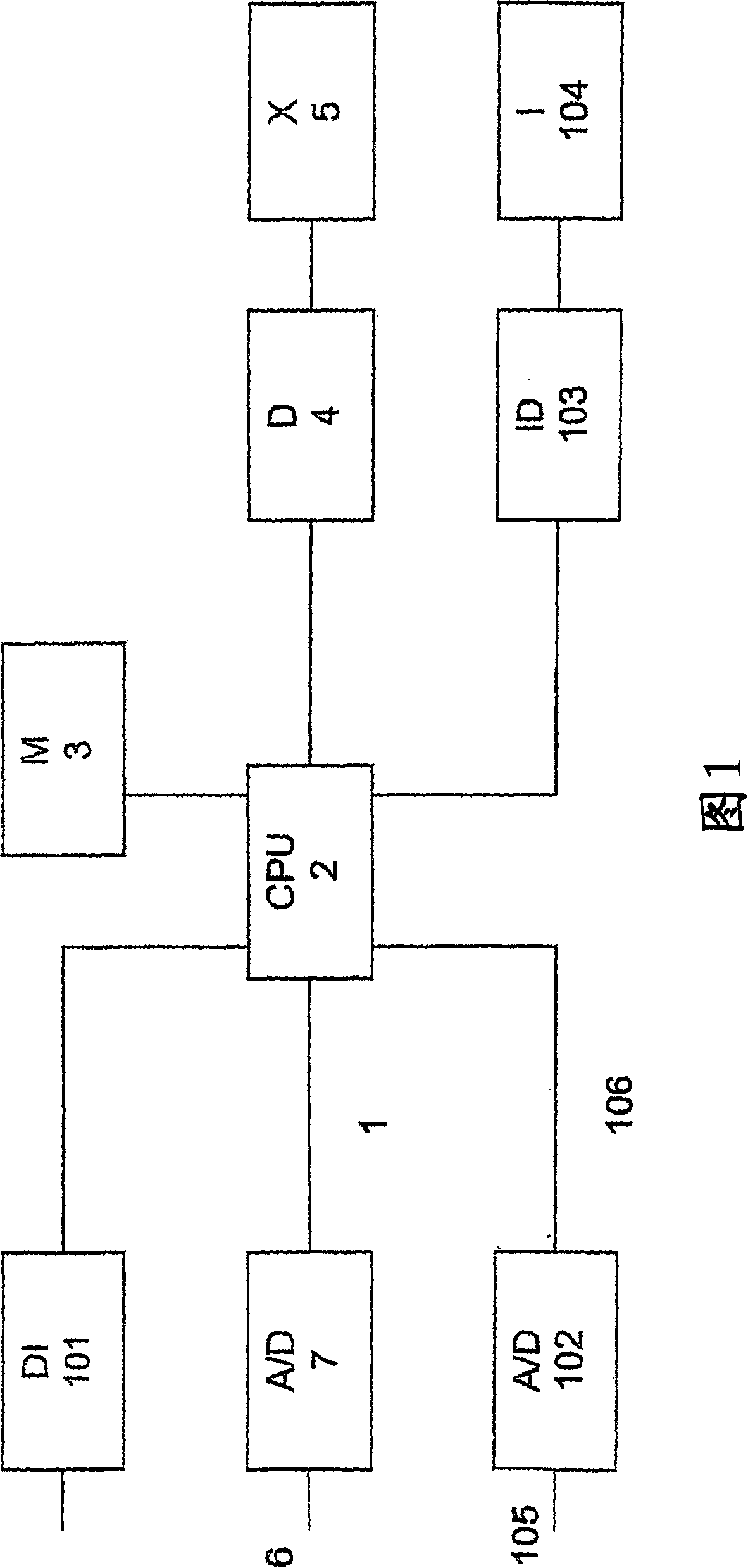
[0035] In the block diagram of the invention shown in FIG. 1 , a digital input terminal 1 is connected to a microprocessor 2 . The microprocessor 2 is connected to a memory 3 containing a map of input / output values ​​with which the microprocessor processes the input values ​​from the terminal 1 before being introduced to the driver 4 . The driver 4 drives the cross-coil meter 5 . The driver 4 converts the signal received from the microprocessor 2 into an analog signal having a different phase. The angles between the different signals ideally place the indicating devices of the cross-coil meter to the same angle. The cross-coil meter 5 can be of different types. For example, the indicating device in the instrument can be rotated 90 degrees, 240 degrees, or more than 360 degrees. Since the cross-coil meter 5 is not perfect, the angle of the pointing device is not always the same as the angle between the signals received from the driver 4 . Digital input terminals can be seri...


PUM


Abstract

The present invention relates to the visual representation of an input value, and provides an instrument, which can be given any predefined characteristic of its visual display. Cross-coil instrument is provided, said cross-coil instrument comprising a driver for the instrument characterized in that it further comprises a digital input terminal, a predetermined characteristic of the instrument stored as a map of input / output values in a digital memory and a microprocessor, said input value being a value represented visually by the cross-coil instrument, said output value being the value applied to the cross-coil instrument to visual represent the input value.

Description

technical field [0001] The present invention relates to a cross-coil meter having predetermined characteristics and a method of imparting such characteristics to the meter. More particularly, the present invention relates to cross-coil meters having highly linear characteristics, or cross-coil meters having different linear constant characteristics in different proportional regions. Background technique [0002] Utilize moving coil meters to make ordinary meters with highly linear characteristics. Its disadvantage is that moving coil meters with highly linear characteristics are expensive. Also, the rotation of the indicating device in moving coil meters is limited because the wires are connected to the rotating device. Another disadvantage of moving coil instruments is that the indicating device must be very light in weight. This makes the meter sensitive to static electricity and makes the meter incapable of being subjected to mechanical stress, which could alter the me...

Claims


Application Information

Patent Timeline
Patent Type & Authority Patents(China)
IPC IPC(8): G01R1/38G01D3/02G01R5/16G01D7/00G01F23/54G01K1/06
CPCG01D3/022G01K1/06G01R1/38
Inventor 芬恩·约翰尼森
Owner 戴夫
Why Eureka
Try Eureka