
RF electronic label with non-action state and its reading system and control method thereof

A technology of electronic tags and action states, which is applied in the direction of instruments, induction record carriers, calculations, etc., can solve problems such as inability to produce actions, and achieve the effect of reducing manufacturing costs

Active Publication Date: 2008-06-11
MITAC INFORMATION TECH CORP
View PDF5 Cites 0 Cited by
  • Summary
  • Abstract
  • Description
  • Claims
  • Application Information

AI Technical Summary

Problems solved by technology

When the output is blocked, the electronic tag can continue to recognize the instructions transmitted by the reader, but cannot produce corresponding actions, such as US Patent Application Publication No. 2002 / 0097143A1, which blocks the output signal at the output terminal

Method used


Image

  • RF electronic label with non-action state and its reading system and control method thereof
  • RF electronic label with non-action state and its reading system and control method thereof
  • RF electronic label with non-action state and its reading system and control method thereof

Examples


Embodiment Construction

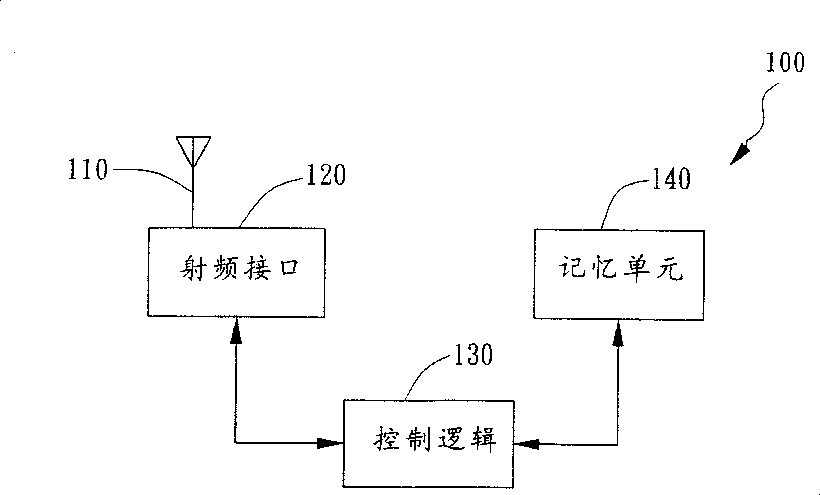
[0015] Such as figure 1 As shown, the passive electronic tag 100 can operate in a sleep mode. The electronic tag 100 has an antenna 110 , a radio frequency interface 120 and a control logic 130 . The electronic tag also has a memory unit 140 . When the electronic tag 100 operates in a low frequency band, LB (for example, 13.56 MHz), the electronic tag 100 can be inductively coupled with a coil of a reader to generate power required by an electronic tag. Or in ultra-high frequency (UHF) or a microwave RFID system, power can be generated by a radio frequency coupling. The radio frequency interface 120 , the control logic 130 and the memory unit 140 can be integrated into an IC, such as a low-power Complementary Metal-Oxide Semiconductor IC. The radio frequency interface 120 is the analog part of the IC, and the control logic 130 and the memory unit 140 are the digital parts of the IC. The memory unit 140 is a non-volatile erasable memory, such as an Electrically Erasable Pro...


PUM


Abstract

A not operating state of RF electric label is not relevant to power, and the not operating state is relevant to function of reset. General speaking, in an example of implementation, the electric label possesses an antenna, a RF interface and control logic. The RF interface is connected to the antenna. Corresponding to an event, the control logic starts a sleep mode. The sleep mode possesses the not operating state, which is not relevant to power. When the not operating state is ended, the control logic provides a follow state, which starts communication mechanism.

Description

technical field [0001] The present invention relates to the design of RFID electronic tags, for example, an RFID chip is used for electronic tag communication and management. Background technique [0002] Traditional RFID electronic tags have some non-action functions, which can be used when reading a large number of RFID electronic tags within a certain range. After a specific electronic tag has been read, when the electronic tag has a power source, the specific electronic tag can be set to an inactive state, so as to prevent the specific electronic tag from being read again. Traditional electronic tags can provide a non-action state. The inactive state is associated with the power supply, for example, a reader or a charge storage device is required to maintain the power supply of the electronic tag (for example, a large capacitor is connected in parallel with the power supply of the electronic tag, when the electronic tag temporarily leaves When the readable range of the...

Claims


Application Information

Patent Timeline
Patent Type & Authority Patents(China)
IPC IPC(8): G06K7/00
Inventor 布鲁斯·罗圣尼
Owner MITAC INFORMATION TECH CORP
Learn More