Speed controlling apparatus of work cylinder

A technology of speed control device and working cylinder, which is applied in the direction of fluid pressure actuator, servo motor, servo meter circuit, etc., can solve the problems of poor control accuracy and high cost, and achieve the effect of improving accuracy, low cost and low cost

Inactive Publication Date: 2008-07-09
WINJET HIGH TECH INVESTMENT BEIJING
View PDF7 Cites 0 Cited by
  • Summary
  • Abstract
  • Description
  • Claims
  • Application Information

AI Technical Summary

Problems solved by technology

These loops need to be composed of more complex components, high cost, and poor control accuracy

Method used


Image

  • Speed controlling apparatus of work cylinder
  • Speed controlling apparatus of work cylinder
  • Speed controlling apparatus of work cylinder

Examples


Embodiment 1

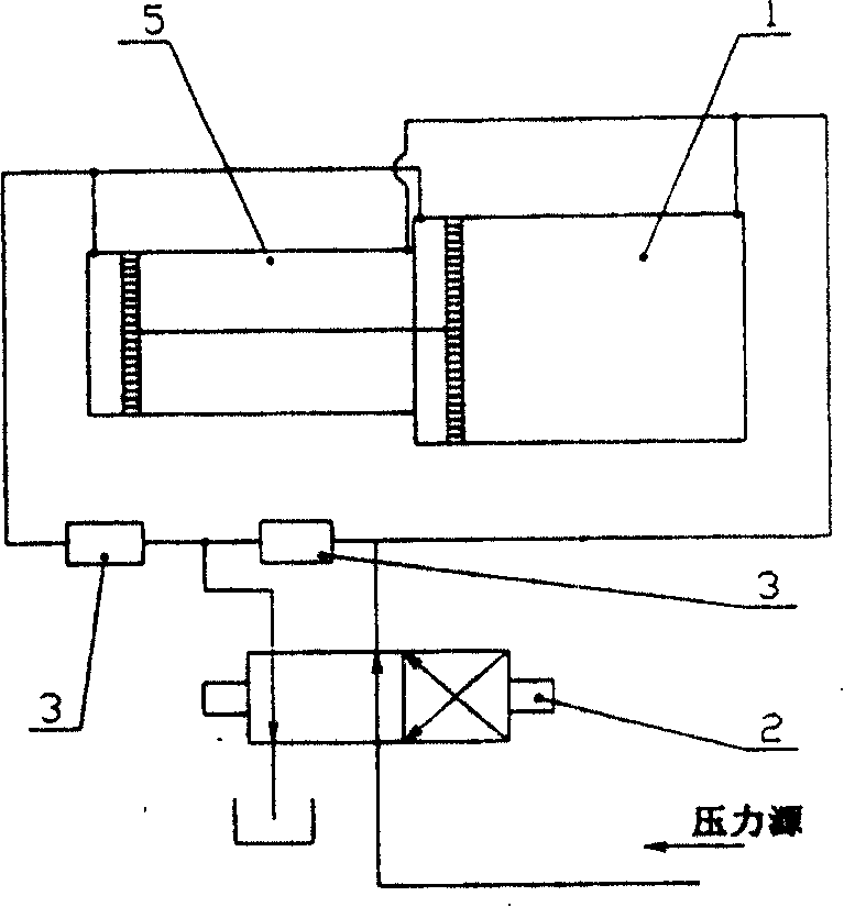
[0025] Such as image 3 As shown, the double working cylinder 1 has a common piston rod 5 connected in parallel, one end of the double cylinder is connected with one end of the first differential flow adjustable shuttle valve 3 and the medium port of the two-position four-way reversing valve 2, and the medium passes through the triple piece from The pressure source enters the reversing valve; the other end of the double cylinder is connected to one end of the second differential flow adjustable shuttle valve 3, and the other end of the first and second differential flow adjustable shuttle valves is connected to the two-position four-way reversing valve. The medium port is connected, and the medium enters the storage tank through the reversing valve. When the reversing valve is reversing, its inlet port and outlet port are exchanged and connected with the above-mentioned elements of the fixed interface.

Embodiment 2

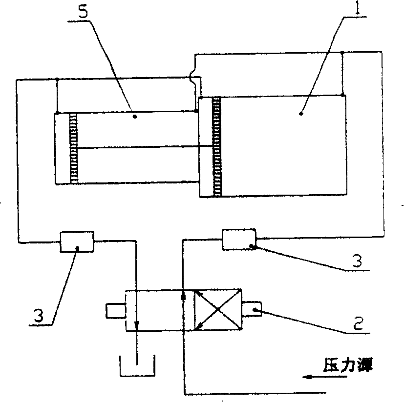
[0027] Such as figure 1 As shown, the double working cylinders 1 have a common piston rod 5 connected in parallel, one end of the double cylinders is connected to one end of the first differential flow adjustable shuttle valve 3, and the other end of the first differential flow adjustable shuttle valve 3 is connected to the two-position four-way The medium outlet of the reversing valve 2 is connected; the other end of the double cylinder is connected to one end of the second differential flow adjustable shuttle valve 3, and the other end of the second differential flow adjustable shuttle valve is connected to the medium of the two-position four-way reversing valve 2 Ingress connection.

Embodiment 3

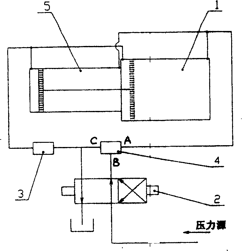
[0029] Such as figure 2 As shown, the double cylinder 1 is connected in series, one end of which is connected to the port A of the shuttle type three-way shunt regulating valve 4, the port B of the shunt regulating valve is connected to the medium inlet port of the two-position four-way reversing valve 2, and the port of the shunt regulating valve C is connected to one end of the differential flow adjustable shuttle valve 3 and the medium outlet port of the two-position four-way reversing valve 2, and the other end of the differential flow adjustable shuttle valve 3 is connected to the other end of the double cylinder.


PUM


Abstract

A control device for a differential flow controllable shuttle valve comprises a directional control valve and a flow control valve in the medium inlet-outlet return circuit of the working cylinder connected with the two-or three-position four-way valve. In the medium inlet or outlet return circuit of the working cylinder is disposed a differential flow controllable shuttle valve.

Description

Technical field: [0001] The present invention relates to a speed control regulator for a pressure cylinder. Background technique: [0002] The speed control loop of the pressure cylinder includes medium, medium control loop bypass throttling control loop, and series-parallel synchronous control loop. These loops need to be composed of multiple components that are relatively complex, with high cost and poor control accuracy. Invention content: [0003] The object of the present invention is to provide a speed control device for a working cylinder with simple structure, few required components, low cost and high control precision. [0004] The present invention is achieved like this: [0005] In the speed control device of the working cylinder of the present invention, the inlet and outlet medium circuits of the working cylinder are connected with a two-position or three-position four-way reversing valve, and there are differential flow adjustable shuttle valves on the med...

Claims


Application Information

Patent Timeline
Patent Type & Authority Patents(China)
IPC IPC(8): F15B11/04
CPCF15B2211/30525F15B2211/413F15B11/04F15B2211/7053F15B2211/46F15B2211/7056F15B2211/428F15B2211/455
Inventor 曾祥炜
Owner WINJET HIGH TECH INVESTMENT BEIJING
Why Eureka
Try Eureka