Method and apparatus for lubricating a bearing assembly

A technology of bearing components, sealing devices, applied in the direction of bearing elements, bearings, shafts and bearings, which can solve the problem of insufficient prevention of pollutants

Inactive Publication Date: 2008-07-16
KORUS JU KEJ LTD
View PDF9 Cites 0 Cited by
  • Summary
  • Abstract
  • Description
  • Claims
  • Application Information

AI Technical Summary

Problems solved by technology

Maintaining bearing integrity against the ingress of undesired impurities or contaminants is also important in some applications, such as production lines, for example in food production lines, where there is a risk of

Method used


Image

  • Method and apparatus for lubricating a bearing assembly

Examples


Embodiment Construction

[0029] The invention will now be illustrated by means of non-limiting examples.

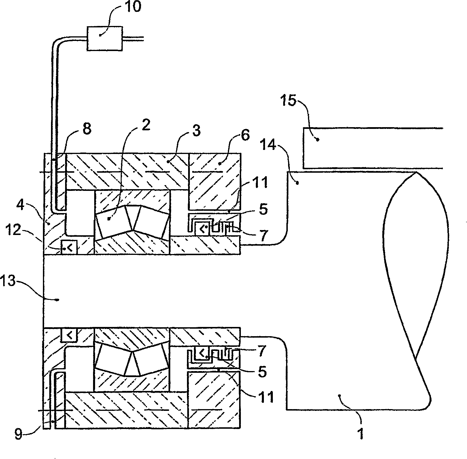
[0030] figure 1 Shows a portion of a roller bearing assembly of a conveyor roll of a continuous casting machine in the steelmaking industry.

[0031]The conveyor rollers 1 are supported by roller elements 2 in bearing housings 3 . The delivery roller comprises a shaft portion 13 and a bearing portion 14 for supporting a load, which is a cast steel plate 15 in this example. The side of the bearing housing closest to the conveyor roller 1 is the inner side of the bearing, and the side of the bearing furthest from the conveyor roller 1 is the outer side. The outer end cover 4 of the bearing housing includes an elastomeric seal 12 positioned to prevent the loss of grease and gas flowing through the outer end cover, thereby forcing it out of the bearing housing on the rollers or the inside of the bearing housing. The inner end cover or inner end seal carrier 6 of the bearing housing comprises seals...


PUM


Abstract

Method of lubricating a bearing assembly and preventing the ingress of contaminants wherein gas is supplied and grease is supplied to the bearing assembly and supplied grease and gas are transported through and discharged from the bearing assembly. The bearing assembly supports a roll neck and comprises a gas supply line (8) and a grease supply line (9) as well as a sealing arrangement (5, 7). The grease and gas are discharged through discharge holes (11).

Description

technical field [0001] The present invention relates to a method of lubricating a bearing assembly and a method of preventing contamination from entering the bearing assembly. The invention also relates to a device for carrying out the method according to the invention. Background technique [0002] Bearing assemblies are used in a very wide range of applications. Lubrication of bearing assemblies is essential. It is also important to maintain the integrity of the bearing components by keeping impurities or contaminants from entering the bearing components and preventing damage that would cause delays and additional costs. This is particularly important in heavy industrial plants, such as rolling mills, where contaminants such as water, other fluids, metal particles, finely divided powders, acids, etc. may be present around bearing components. Maintaining the integrity of the bearing against the ingress of undesired impurities or contaminants is also important in some app...

Claims


Application Information

Patent Timeline
IPC IPC(8): F16C33/66F16N7/32F16C13/02F16C33/76B21B31/07F16N7/30
CPCF16C13/02F16C33/6622F16N2210/14F16N7/30F16C33/76
Inventor D·A·普雷肖
Owner KORUS JU KEJ LTD
Why Eureka
Try Eureka