Supercharge Your Innovation With Domain-Expert AI Agents!

Excimers lamp luminous device

A technology of excimer lamps and light-emitting devices, which is applied in the direction of discharge lamps, parts of gas discharge lamps, electrical components, etc., and can solve problems such as inability to output ultraviolet luminous flux and unbalanced radiated luminous flux

Inactive Publication Date: 2008-08-06
USHIO DENKI KK
View PDF5 Cites 0 Cited by
  • Summary
  • Abstract
  • Description
  • Claims
  • Application Information

AI Technical Summary

Problems solved by technology

In other words, due to the distortion of the dielectric material, there may be problems such as inability to output the desired ultraviolet luminous flux, or local reduction of the radiated luminous flux, etc.

Method used


Image

  • Excimers lamp luminous device
  • Excimers lamp luminous device
  • Excimers lamp luminous device

Examples


Embodiment Construction

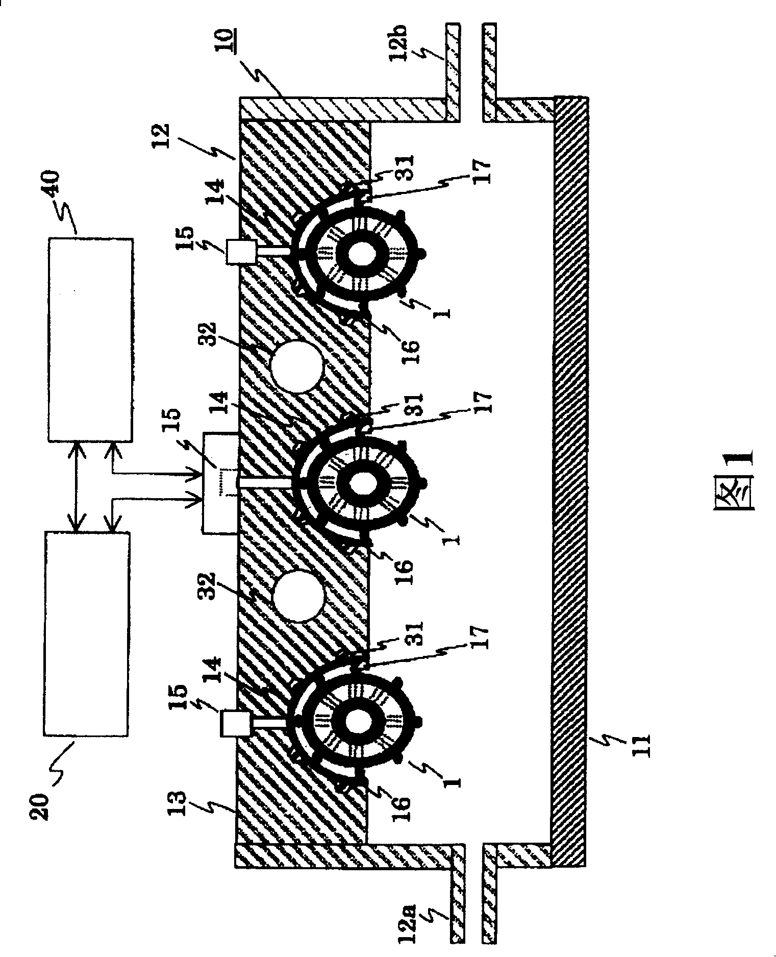
[0035] Fig. 1 shows an excimer lamp light-emitting device of the present invention. The interior of the lighting device 10 is provided with an excimer lamp 1 . The lighting device 10 is composed of a light output surface 11 , a main body cabinet 12 and a metal block 13 . The light output surface 11 is permeable to vacuum ultraviolet light emitted from the excimer lamp, and is made of, for example, synthetic quartz glass. The main body casing 12 is made of, for example, stainless steel, and a gas inlet 12a is formed on one side wall thereof, and a gas discharge port 12b is formed on the other side wall. As a result, an inert gas such as nitrogen gas is introduced into the gas introduction port 12a, and remaining oxygen and inert gas are discharged from the discharge port 12b.

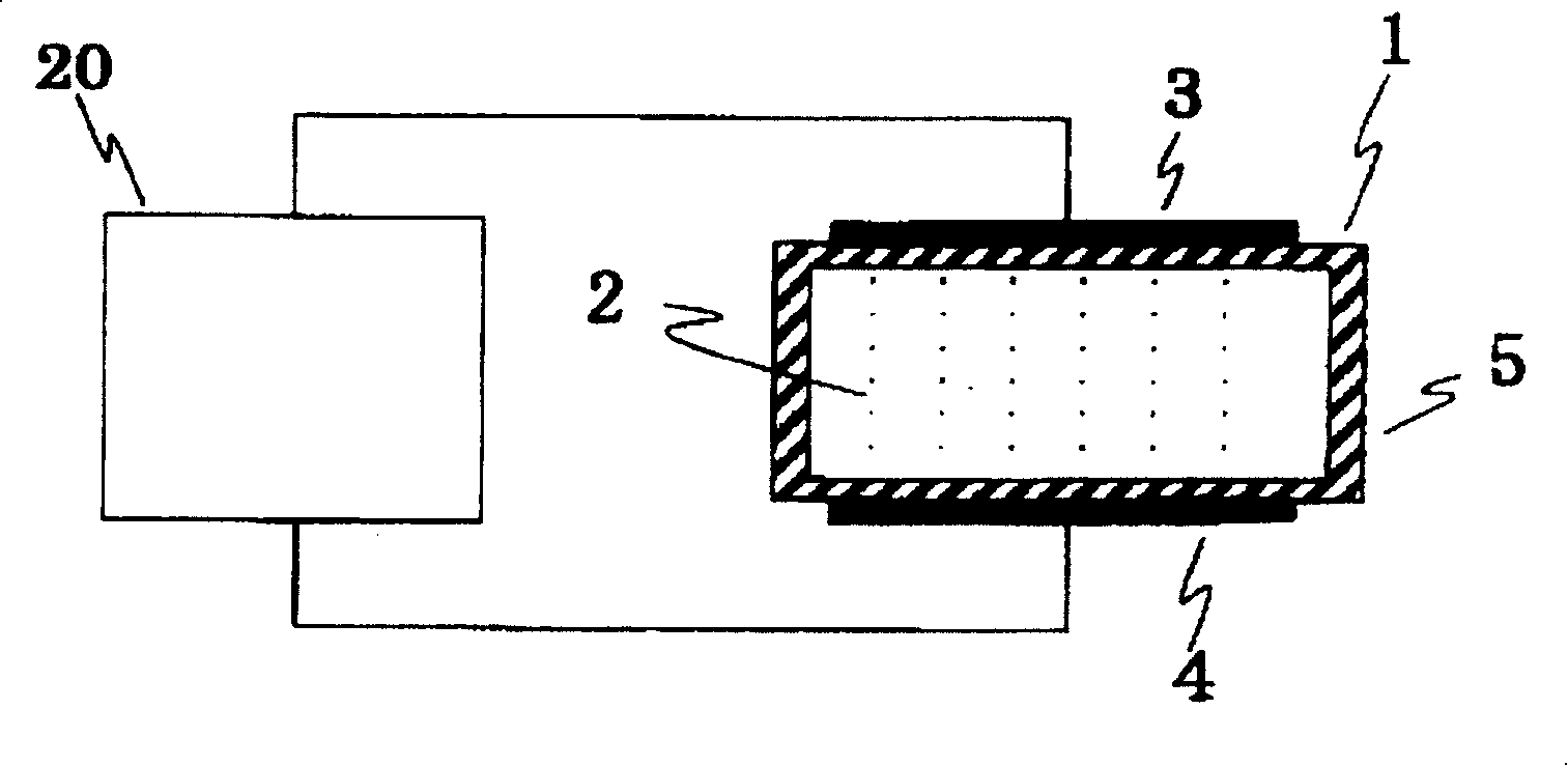
[0036] Outside the lighting device 10 there is a power supply device 20 for supplying electric power to the excimer lamps 1 , and each excimer lamp 1 is electrically connected by wires or the like. In...


PUM


Abstract

To maintain discharge start voltage of an excimer lamp at a constant level, and to uniform the light emission rate in terms of time and location. The excimer lamp light emitting device comprises an excimer lamp for emitting a vacuum ultraviolet light by discharging through a dielectric material, a power supply device for supplying a predetermined power to the excimer lamp, temperature control means for increasing / decreasing the temperature of the excimer lamp, and a control part for detecting the temperature of the excimer lamp and for maintaining the lamp at a predetermined target temperature. In order to maintain the discharge start voltage of the excimer lamp at an approximately constant level, the power supply device maintains the excimer lamp at a target temperature higher than room temperature approximately constantly through the control part, even before the excimer lamp is turned on.

Description

technical field [0001] The invention relates to an excimer lamp light-emitting device. In particular, it relates to a discharge lamp used as an ultraviolet light source for photochemical reactions, an excimer lamp light-emitting device that forms excimers by discharge of a dielectric material, and utilizes light emitted by the excimers. Background technique [0002] The technology related to this invention is, for example, JP-A No. 2-7353, which describes an emitter, that is, an excimer lamp. This emitter fills the discharge vessel with a discharge gas that can form excimers, and discharges through a dielectric barrier layer (also known as ozone generator discharge or silent discharge. Refer to the revised version of the "Discharge Handbook" issued by the Electrical Society, Heisei 1 Year 6 7th print issue, July reprint, p. 263) forms an excimer, and outputs the light emitted by the excimer. [0003] The discharge vessel of this excimer lamp has a cylindrical shape, at lea...

Claims


Application Information

Patent Timeline
Patent Type & Authority Patents(China)
IPC IPC(8): H01J65/00H01J65/04H01J61/52
CPCH01J61/56
Inventor 中村雅规清濑正秀
Owner USHIO DENKI KK
Features
  • R&D
  • Intellectual Property
  • Life Sciences
  • Materials
  • Tech Scout
  • Unparalleled Data Quality
  • Higher Quality Content
  • 60% Fewer Hallucinations
Learn More