Diversity antenna assembly with function of multiple inupts and outputs in wireless communication base station
A wireless communication and diversity antenna technology, applied in diversity/multi-antenna systems, antennas, antenna arrays, etc., can solve problems that are not suitable for wireless MIMO channel diversity reception and transmission
- Summary
- Abstract
- Description
- Claims
- Application Information
AI Technical Summary
Problems solved by technology
Method used
Image
Examples
Embodiment 1
[0118] Embodiment 1: A base station diversity antenna device composed of a four-element Yagi antenna with a cylindrical shared reflector
[0119] Figure 10 It is a top view of the multi-antenna device, which consists of four pairs of directional antennas uniformly distributed around the antenna support rod in the azimuth direction and a cylindrical shared reflector fixed around the antenna support rod.
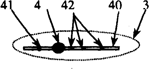
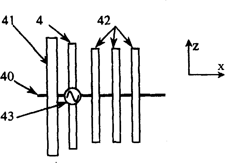
[0120] Among them, 8 is a common metal reflector surrounding and fixed on the antenna support rod 2, with a diameter of 5.4 wavelengths. On the one hand, it serves as the public reflector of the Yagi antenna, on the other hand, it plays a role in enhancing scattering and can strengthen the antenna device. 1 is an antenna bracket, 2 is an antenna support rod, 3 is a directional antenna, and x and y are coordinate axes. The directional antenna 3 employs a similar image 3 The four-element Yagi antenna, whose center frequency is 2.15GHz, uses a coaxial cable to connect the act...
Embodiment 2
[0126] Embodiment 2: A base station diversity antenna device composed of four-element Yagi antennas without a shared reflector
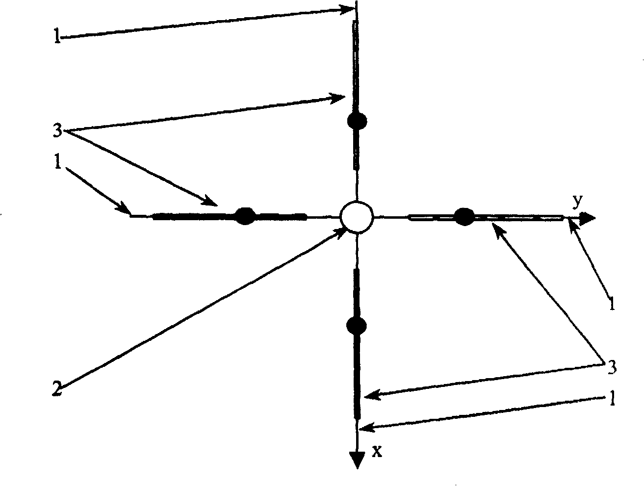
[0127] figure 1A top view of a diversity antenna composed of four-element Yagi antennas without a common reflector as a second embodiment of the present invention. Wherein, 1 is an antenna bracket, 2 is an antenna support rod, 3 is a directional antenna, and x and y are coordinate axes. The directional antenna 3 employs a similar image 3 The four-element Yagi antenna with a center frequency of 2.15 GHz uses a coaxial cable to connect the active unit 4 and the receiver or transmitter to form a feeding device. The antenna support in the diversity antenna device is used to support the antenna device, and the distance between the reflectors of two opposite Yagi antennas is 5.4 wavelengths.
[0128] figure 1 The H-plane far-field pattern of a pair of quadruple Yagi antennas in Figure 15 , figure 1 The E-plane far-field pattern of a pair of four-el...
Embodiment 3
[0132] Embodiment 3: Diversity antenna device composed of four-element Yagi antennas with external electromagnetic scatterers and no shared reflector
[0133] The third embodiment of the present invention is based on the second embodiment, in figure 1 An electromagnetic scatterer 9 is placed near the diversity antenna composed of four-element Yagi antennas without a shared reflector, and its schematic diagram is shown in Figure 11 , four pairs of directional antennas are evenly distributed around the antenna support pole along the azimuth direction, and a plurality of external electromagnetic scatterers 9 are placed near the directional antennas. Wherein, 1 is an antenna bracket, 2 is an antenna support rod, 3 is a directional antenna, and x and y are coordinate axes. The directional antenna 3 employs a similar image 3 The four-element Yagi antenna with a center frequency of 2.15GHz uses a coaxial cable to connect the active unit and the receiver or transmitter to form a f...
PUM
 Abstract
Description
Claims
Application Information
 - R&D
- Intellectual Property
- Life Sciences
- Materials
- Tech Scout
- Unparalleled Data Quality
- Higher Quality Content
- 60% Fewer Hallucinations
Browse by: Latest US Patents, China's latest patents, Technical Efficacy Thesaurus, Application Domain, Technology Topic, Popular Technical Reports.
© 2025 PatSnap. All rights reserved.Legal|Privacy policy|Modern Slavery Act Transparency Statement|Sitemap|About US| Contact US: help@patsnap.com


