Catalyzing cracking slurry oil topping tech. and industry apparatus thereof

A technology of catalytic cracking oil slurry and process equipment, which is applied in the field of catalytic cracking oil slurry topping process and industrial equipment, which can solve the problems of reducing wax content, high wax content, low flash point, etc., and achieves flexible operation and wide adaptability of raw materials Effect

Inactive Publication Date: 2008-09-03
CHINA PETROLEUM & CHEM CORP
View PDF4 Cites 0 Cited by
  • Summary
  • Abstract
  • Description
  • Claims
  • Application Information

AI Technical Summary

Problems solved by technology

The test found that: the light component wax content of catalytic cracking oil slurry is high, and the flash point (opening) is low. Although some light components in the catalytic cracking oil slurry can be removed with a general vacuum distillation device, it cannot effectively improve the catalytic cracking oil. flash point of pulp and reduce its wax content
Therefore, there are relatively large technical defects in the treatment of catalytic cracking oil slurry by this method
In addition, this method does not make a specific description of the vacuum distillation process of catalytic cracking oil slurry

Method used


Image

  • Catalyzing cracking slurry oil topping tech. and industry apparatus thereof
  • Catalyzing cracking slurry oil topping tech. and industry apparatus thereof
  • Catalyzing cracking slurry oil topping tech. and industry apparatus thereof

Examples


Embodiment 1

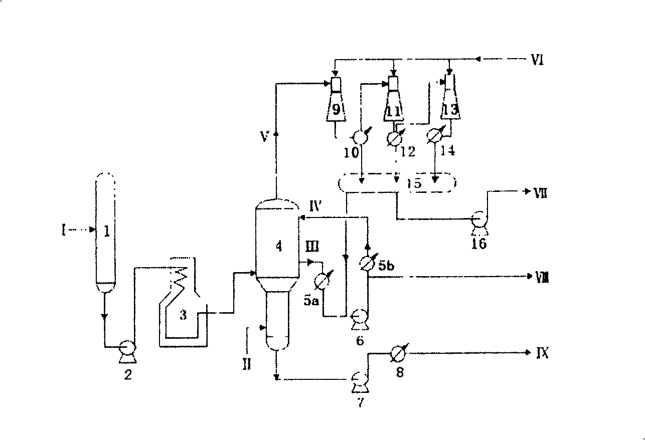
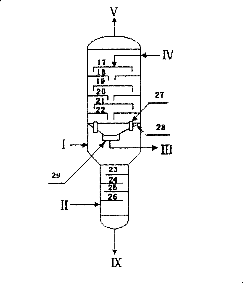
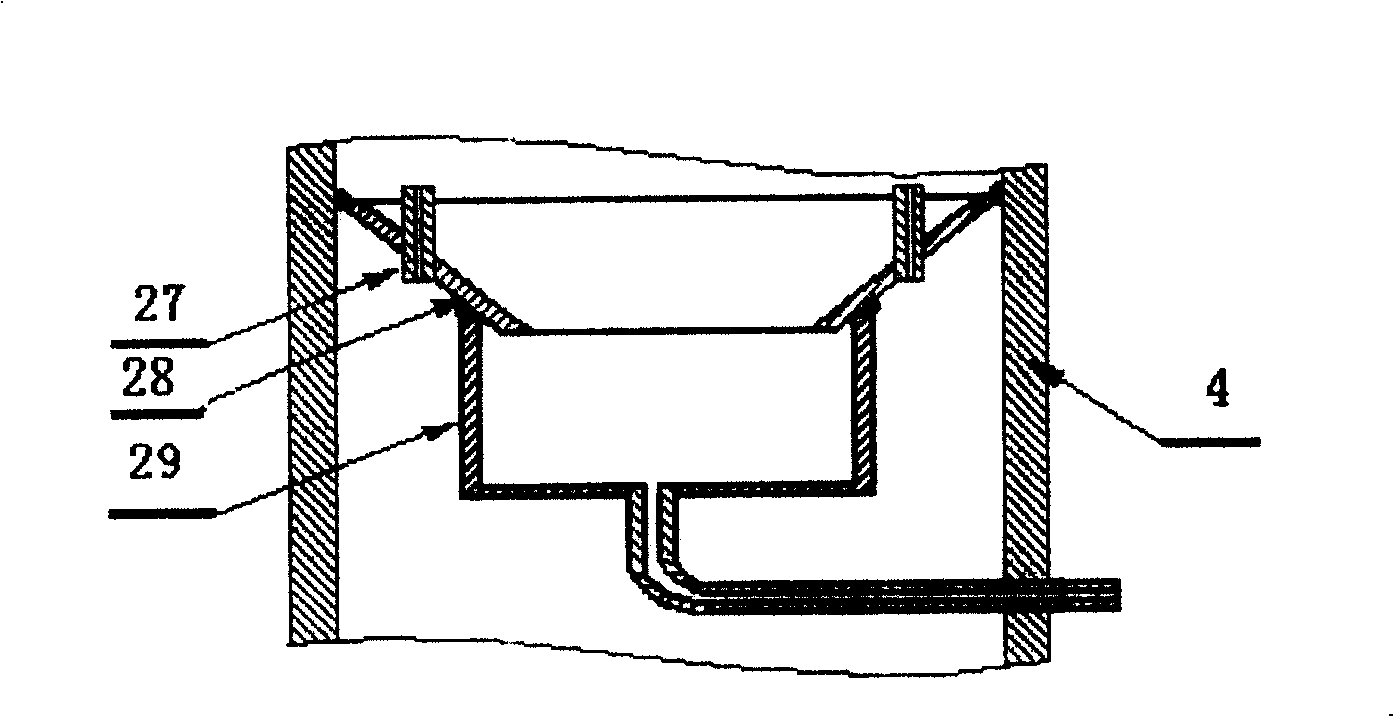
[0028] The catalytic cracking oil slurry topping process proposed in this embodiment is: the catalytic cracking oil slurry I is heated to 350 ° C and then continuously enters the oil slurry topping tower. Under the operating pressure of 0.5Kpa, it is vaporized and separated into light and heavy. Components, the light components are all extracted from the light oil slurry collector located between the rectification section and the stripping section, part of which is used as raw material for visbreaking, delayed coking or thermal cracking devices after primary cooling, and the other part is used for secondary After being cooled to 70 DEG C, return the oil slurry head tower from the top of the rectifying section as the cold reflux at the top of the tower; After the hot water steam is stripped, it is drawn from the bottom of the tower, cooled to 90°C by the heavy oil slurry cooler 8, and then sent to the asphalt blending facility to blend soft components.

[0029] In this embodime...

Embodiment 2

[0034] The catalytic cracking oil slurry topping process proposed in this embodiment is: the catalytic cracking oil slurry I is heated to 324 ° C and then continuously enters the oil slurry topping tower. Under the operating pressure of 2.0Kpa, it is separated into light and heavy after vaporization. Components, the light components are all extracted from the light oil slurry collector located between the rectification section and the stripping section, part of which is used as raw material for visbreaking, delayed coking or thermal cracking devices after primary cooling, and the other part is used for secondary After being cooled to 95°C, return the oil slurry head tower from the upper part of the rectification section as a cold reflux at the top of the tower; the superheated stripping steam consumption of the heavy component in the stripping section is 1.8% (weight) superheat of the oil slurry feed amount After steam stripping, it is drawn from the bottom of the tower, cooled...

Embodiment 3

[0037] The catalytic cracking oil slurry topping process proposed in this embodiment is: the catalytic cracking oil slurry I is heated to 290 ° C and then continuously enters the oil slurry topping tower. Under the operating pressure of 3.0Kpa, it is separated into light and heavy after vaporization. Components, the light components are all extracted from the light oil slurry collector located between the rectification section and the stripping section, part of which is used as raw material for visbreaking, delayed coking or thermal cracking devices after primary cooling, and the other part is used for secondary After cooling to 110°C, return the oil slurry topping tower from the upper part of the rectification section as a cold reflux at the top of the tower; the superheated stripping steam consumption of the heavy component in the stripping section is 1% (weight) superheat of the oil slurry feed amount After steam stripping, it is taken out from the bottom of the tower, coole...


PUM

PropertyMeasurementUnit
densityaaaaaaaaaa
densityaaaaaaaaaa

Abstract

This invention belongs to the fuel chemical industry technology area, it mainly relates to the catalytic cracking slurry topping and its industry device. The slurry materials are heated to 290-360 deg.C and then they are added into the slurry topping tower continuously. The slurry is evaporated into light and heavy components under the operational pressure of 0.5-5 Kpa, and the light component is totally pulled out from the light oil collector which is between the rectifying and extracting tower. After the light oil is cooled, one part of the light oil can be as cold circumfluence of the tower top, and the other part can be as the material of the viscosity breaking, delayed coke and thermal cracking device. The heavy component is pulled out from the bottom of the tower after it is extracted by the overheat water vapor in the extracting part. It is supplied to the asphalt tempered device as the soft tempered component of the asphalt to construct high lever road, the density of it is higher than 1.05g / cm3, the content of wax is lower than 3.0%, and the flash point higher than 230 deg.C. It is suitable to be the soft tempered component of the asphalt to construct high lever road. The material buffer tank, slurry topping tower, heating furnace, pump, cooler and the other off-set device match with this technology, and it can realize the continuous operation of this technology. This invention can save the energy, have high efficiency, operate smart and the adaptability of material is extensive.

Description

technical field [0001] The invention belongs to the technical field of petrochemical industry, and mainly relates to a continuous catalytic cracking oil slurry topping process and an industrial device. This technology is suitable for providing raw materials for visbreaking units, delayed coking units, thermal cracking units and asphalt blending, especially suitable for providing blending soft components for propane or butane deoiled hard asphalt to produce high-grade road petroleum asphalt. Background technique [0002] my country is a country dominated by paraffin-based crude oil, and the resources available for the production of road asphalt (especially high-grade road asphalt) are limited. The main problems affecting the quality of road asphalt are the high wax content of asphalt, colloids and aromatic components. Relatively small. Catalytic cracking oil slurry is a by-product of petroleum refining process, its main components are aromatic components and colloids, in addi...

Claims


Application Information

Patent Timeline
Patent Type & Authority Patents(China)
IPC IPC(8): C10G31/00
Inventor 赵振辉任满年杨书显杨英侠杨志强柴志杰黄建林徐武清
Owner CHINA PETROLEUM & CHEM CORP
Why Eureka
Try Eureka