
Motor driving device

A technology of motor drive and equipment, applied in heating/cooling equipment, controlling multiple AC motors, multiple motor speed adjustments, etc., can solve problems such as adverse effects

Inactive Publication Date: 2008-09-24
DENSO CORP
View PDF4 Cites 2 Cited by
  • Summary
  • Abstract
  • Description
  • Claims
  • Application Information

AI Technical Summary

Problems solved by technology

Oscillation of the oscillating circuit 31 produces undesired radiation which can adversely affect other equipment such as audio equipment (e.g. radio), video equipment (e.g. television), etc.

Method used


Image

  • Motor driving device
  • Motor driving device
  • Motor driving device

Examples


Embodiment Construction

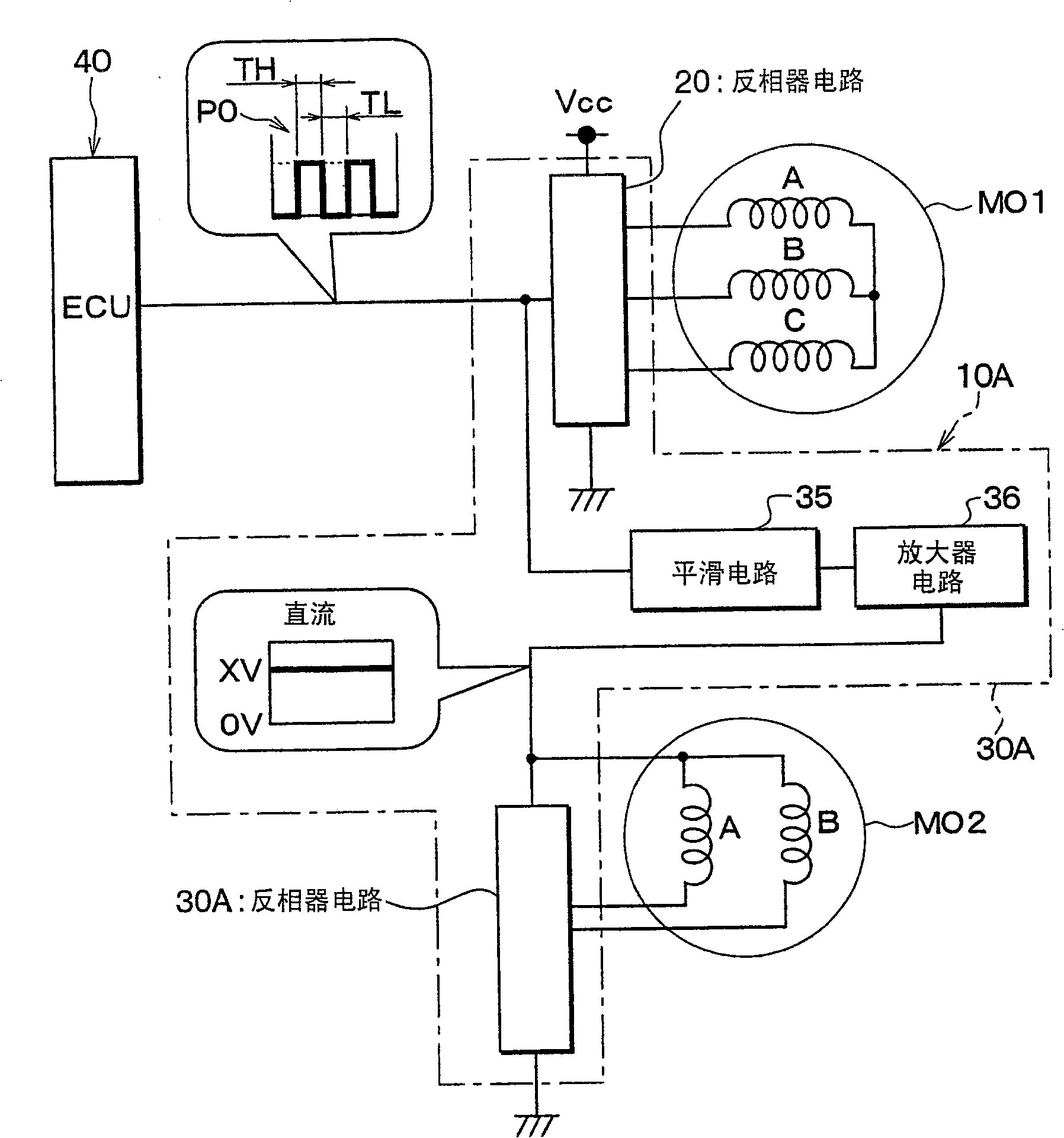
[0021] refer to figure 1 , to illustrate the motor drive apparatus 10A. In one embodiment, the motor-driven device 10A is used for a blower in a vehicle air conditioner. However, it will be appreciated that the motor drive apparatus 10A may also be used for any other suitable purpose. exist figure 1 , the same reference signs are given as image 3 The components corresponding to those components in .

[0022] The motor drive device 10A includes inverter circuits 20A, 30A, a smoothing circuit 35 , and an amplifier circuit 36 ​​. In one embodiment, the inverter circuit 20 of the present embodiment is widely known (eg, with image 3 The inverter circuit 20 shown is substantially the same).

[0023] The smoothing circuit 35 includes a smoothing capacitor and the like, and smoothes the pulse signal P0 output from the electronic control unit 40 . The amplifier circuit 36 ​​amplifies the voltage output from the smoothing circuit 35, and applies the amplified voltage to the sin...


PUM


Abstract

A motor driving device is disclosed that includes a first drive circuit that drives a first electric motor and increases a rotational speed of the first electric motor according to an increase in a duty ratio of a pulse signal output from an electronic control unit. The motor driving device also includes a second drive circuit that drives a second electric motor and increases the rotational speed of the second electric motor according to the increase in the duty ratio of the pulse signal. The second drive circuit smooths the pulse signal from the electronic control unit to produce a direct-current voltage. Also, the second drive circuit supplies electric power to the second electric motor by applying the direct-current voltage to the second electric motor.

Description

technical field [0001] The present invention relates to a motor drive device for driving a plurality of motors Background technique [0002] A vehicle air conditioning system has been proposed that has a plurality of electric blowers (for example, two blowers) and a motor-driven device that drives each blower. E.g, image 3 A conventional configuration of a circuit of a motor drive device is shown. [0003] The motor drive device 10 includes inverter circuits 20 , 30 , an oscillation circuit 31 , and field effect transistors 32 , 33 . The inverter circuit 20 drives the three-phase brushless motor MO1 for the hair dryer according to the pulse signal P0 output from the electronic control unit 40 (ECU). [0004] More specifically, the stator of the three-phase brushless motor MO1 has armature windings A, B, C, and the armature windings A, B, C provide a rotating magnetic field to the rotor. When the duty cycle of the pulse signal P0 increases, the inverter circuit 20 increas...

Claims


Application Information

Patent Timeline
Patent Type & Authority Patents(China)
IPC IPC(8): H02P5/46H02P5/60H02P5/74
CPCB60H1/00428Y02T10/88
Inventor 桑田胜治
Owner DENSO CORP
Learn More