
LCD device

A technology of liquid crystal display and liquid crystal layer, which is applied in the direction of static indicators, etc., can solve the problems of component damage, increase the thickness of the display 100, complexity, manufacturing cost, and complicated operation process, so as to simplify the structure and manufacturing cost, and improve the display quality , the effect of good alignment quality

Active Publication Date: 2008-10-15
TSINGHUA UNIV +1
View PDF3 Cites 0 Cited by
  • Summary
  • Abstract
  • Description
  • Claims
  • Application Information

AI Technical Summary

Problems solved by technology

[0008] The operation process of this contact manufacturing method that relies on flannelette rollers to brush and grind the alignment material is relatively complicated, and a large amount of static electricity is easily introduced during the operation process, which is easy to damage the thin film transistor (Thin Film Transistor, TFT) element in the liquid crystal display 100. Causes damage; produces a lot of dust and requires additional cleaning steps so as not to affect the quality of the resulting alignment film
And, the life-span of the flannelette that adopts is limited, needs to change frequently
[0009] In addition, the polarizers 102, 110, and the transparent electrode layers 106, 114 also play an important role in realizing liquid crystal display in the liquid crystal display 100, but the existence of the multiple sheet structures and their interfaces will increase the thickness of the display 100, Complexity and manufacturing cost reduce the transmittance of the light provided by the backlight and affect the display quality

Method used


Image

  • LCD device
  • LCD device
  • LCD device

Examples


Embodiment Construction

[0017] The present invention will be further described in detail below in conjunction with the accompanying drawings.

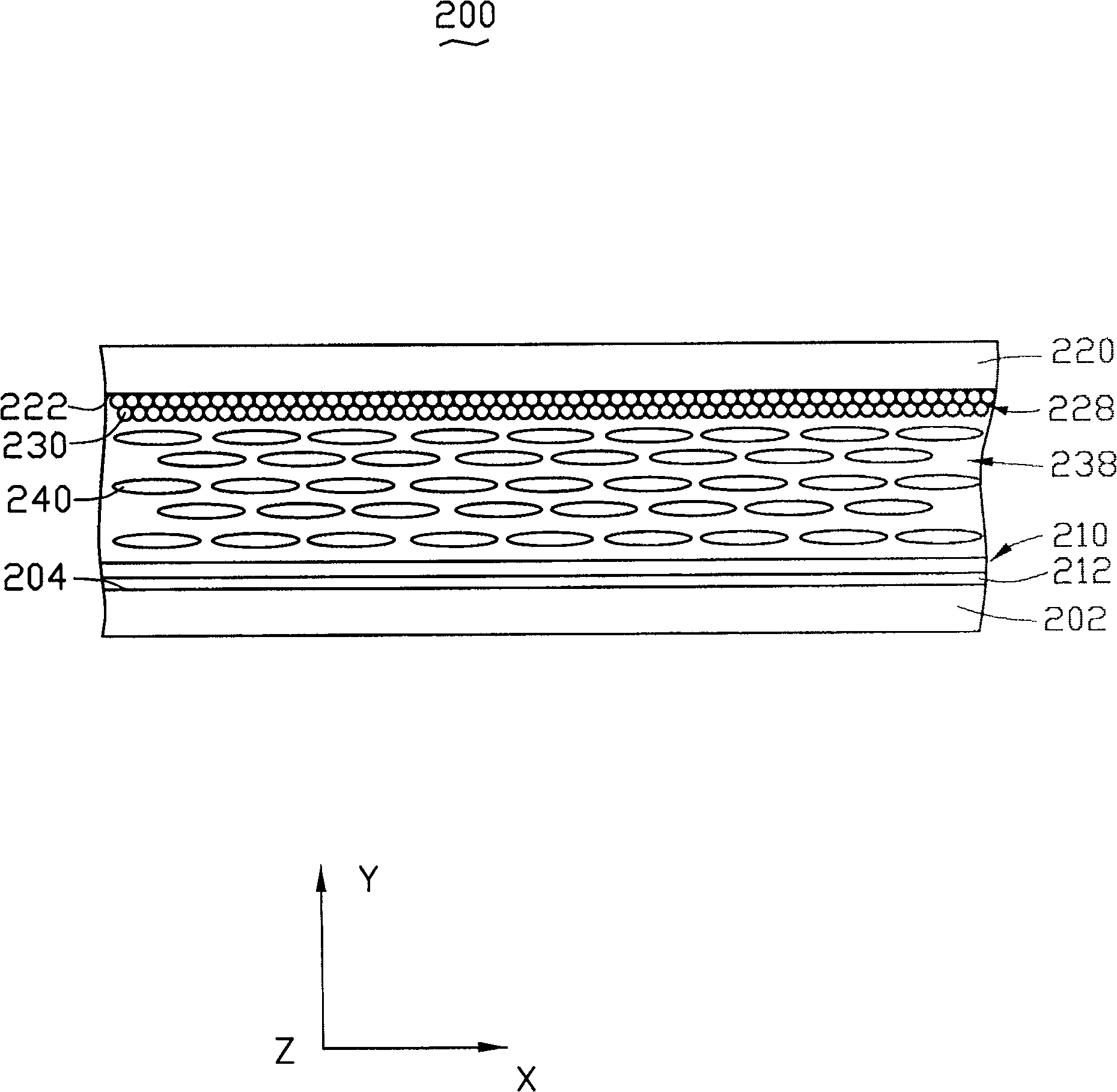
[0018] like figure 2 Shown is a schematic cross-sectional view of the liquid crystal display of this embodiment. The liquid crystal display 200 mainly includes a first substrate 202 , a second substrate 220 and a liquid crystal layer 238 .

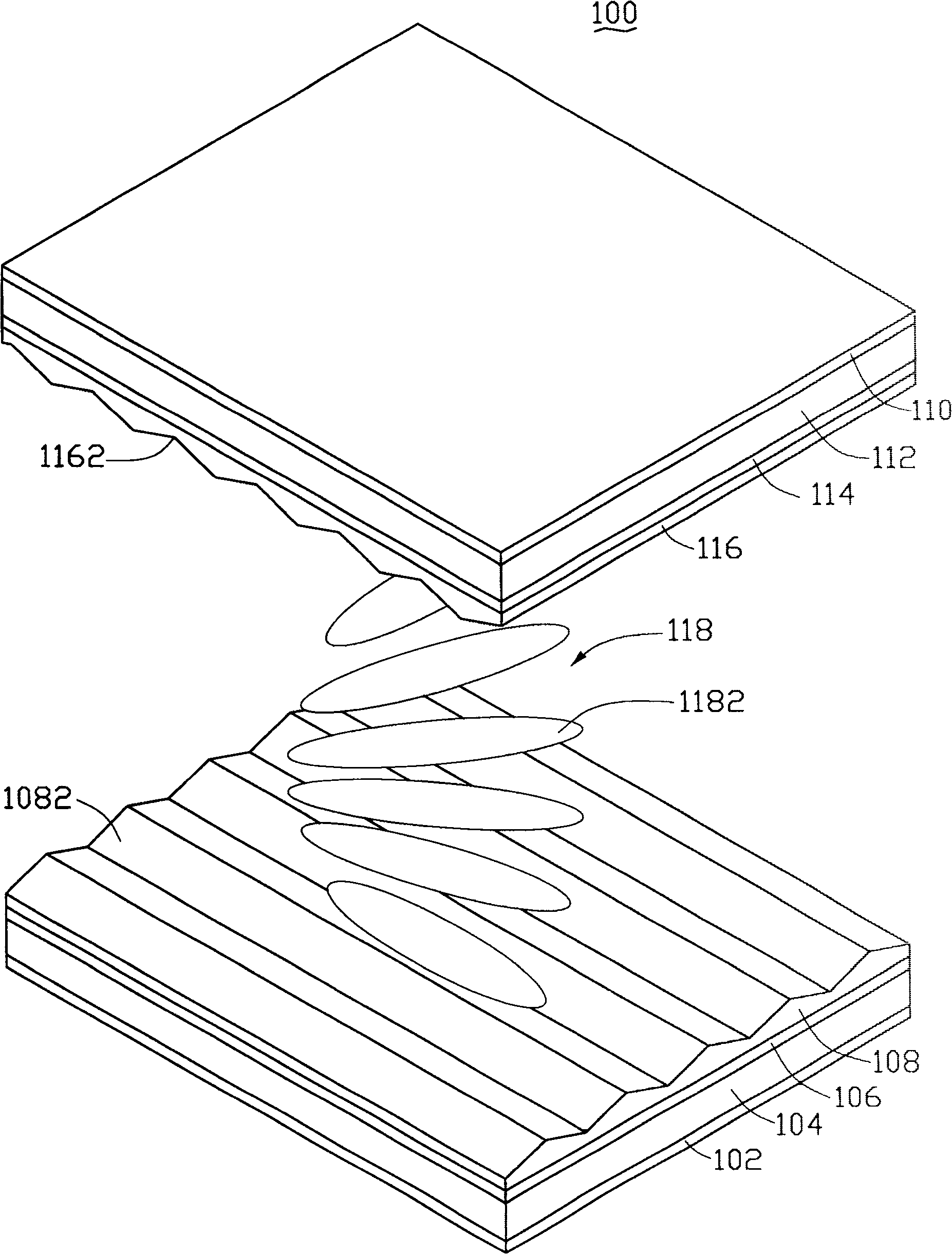
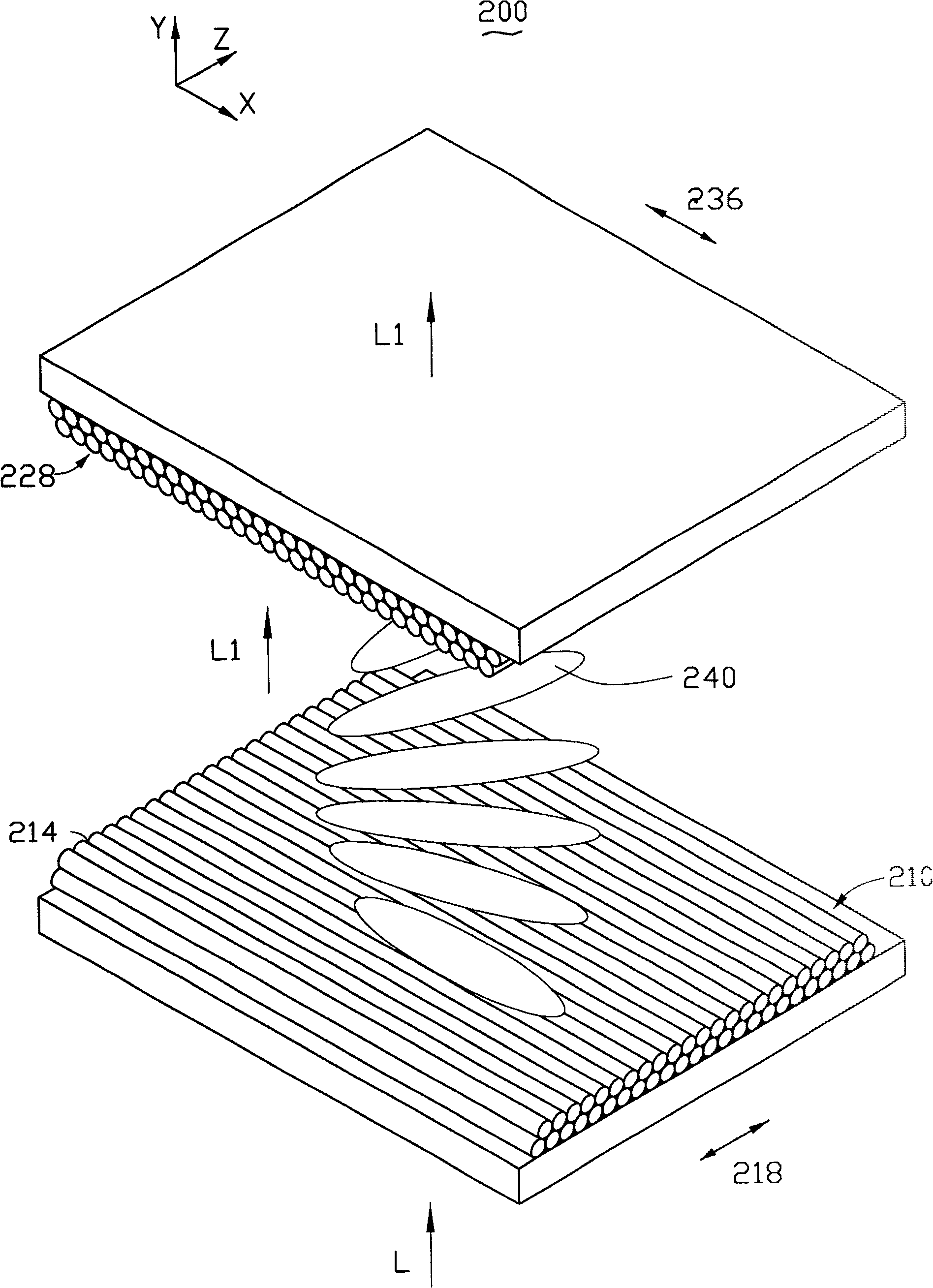
[0019] The first substrate 202 is opposite to the second substrate 220 . The first substrate 202 is usually a thin film transistor substrate, and the second substrate 220 is usually a color filter (Color Filter, CF) substrate. The liquid crystal layer 238 includes a plurality of long rod-shaped liquid crystal molecules 240 , and the liquid crystal layer 238 is sandwiched between the first substrate 202 and the second substrate 220 . A first nanomaterial thin layer 210 is disposed on the inner surface 204 of the first substrate 202 , and a second nanomaterial thin layer 228 is disposed on the inner surface 222 of the s...


PUM

PropertyMeasurementUnit
thicknessaaaaaaaaaa
thicknessaaaaaaaaaa

Abstract

The invention discloses a LCD display, aimed at resolving the existing technology of LCD display complicated structure and assigned to film distribution to the poor quality of the issue. The invention of the LCD substrate includes the first, second substrates, the liquid crystal layer and the first distribution to the electrode polarization layers. The first substrate and the second substrate are relative setup. The liquid crystal layer is folded between the first substrate and the second substrate. The polarization assigned to the first electrode layer is placed in the first LCD substrate layers near the surface. The polarization assigned to the first electrode layer is made of several parallel with a one dimensional nanostructures formation of thin rope. The polarization assigned to the first electrode layer is polarized, conductive and distribution of liquid crystal molecules to the role.

Description

technical field [0001] The invention relates to a liquid crystal display. Background technique [0002] In recent years, liquid crystal displays with the advantages of thinness, lightness, and low power consumption have been widely used in displays such as personal computers, mobile phones, televisions, cameras, and measuring instruments. [0003] like figure 1 Shown is a perspective view of a liquid crystal display in the prior art. The liquid crystal display 100 generally includes a first substrate 104, a second substrate 112 and a liquid crystal layer 118 sandwiched therebetween. [0004] The first substrate 104 is opposite to the second substrate 112 . The liquid crystal layer 118 includes a plurality of long rod-shaped liquid crystal molecules 1182 . A first transparent electrode layer 106 and a first alignment film 108 are sequentially disposed on the inner surface of the first substrate 104 , and a first polarizer 102 is disposed on the outer surface of the first ...

Claims


Application Information

Patent Timeline
Patent Type & Authority Patents(China)
IPC IPC(8): G02F1/133
Inventor 刘亮姜开利范守善
Owner TSINGHUA UNIV
Features
  • Generate Ideas
  • Intellectual Property
  • Life Sciences
  • Materials
  • Tech Scout
  • Unparalleled Data Quality
  • Higher Quality Content
  • 60% Fewer Hallucinations
Learn More