Completely non - contacting magnetic suspension control moment gyro of single framework

A technology for controlling moment gyroscopes and magnetic levitation. It is applied in the direction of rotating gyroscopes and aerospace vehicle guidance devices. It can solve the problems of large size and weight of the frame system, affecting the stability of the spacecraft, and interference with the spacecraft system, so as to reduce the volume. and weight, improve reliability and service life, and reduce the effect of bonding area

Inactive Publication Date: 2008-11-26
BEIHANG UNIV
View PDF4 Cites 0 Cited by
  • Summary
  • Abstract
  • Description
  • Claims
  • Application Information

AI Technical Summary

Problems solved by technology

The existing single-frame control moment gyroscope, the gyroscope rotor system and the frame system are all supported by mechanical bearings. Due to the wear of the mechanical bearings, there are still many restrictions on the speed and service life of the rotor system. At the same time, due to the friction torque of the mechanical shaft of the frame system It is nonlinear, which will bring a disturbance torque to the spacecraft system, thereby affecting the stability of the spacecraft; the existing single-frame control moment gyroscopes are all supported at both ends, such as attached figure 1 , the frame system has two support points (support point 1, 2), the frame system of the control moment gyroscope of this structure needs to provide the turning space for the rotor system, so the volume and weight of the frame system are relatively large, and it is different from the satellite’s mechanical The interface is also relatively large, not suitable for control torque gyroscopes with small and medium torque output

Method used


Image

  • Completely non - contacting magnetic suspension control moment gyro of single framework
  • Completely non - contacting magnetic suspension control moment gyro of single framework
  • Completely non - contacting magnetic suspension control moment gyro of single framework

Examples


Embodiment Construction

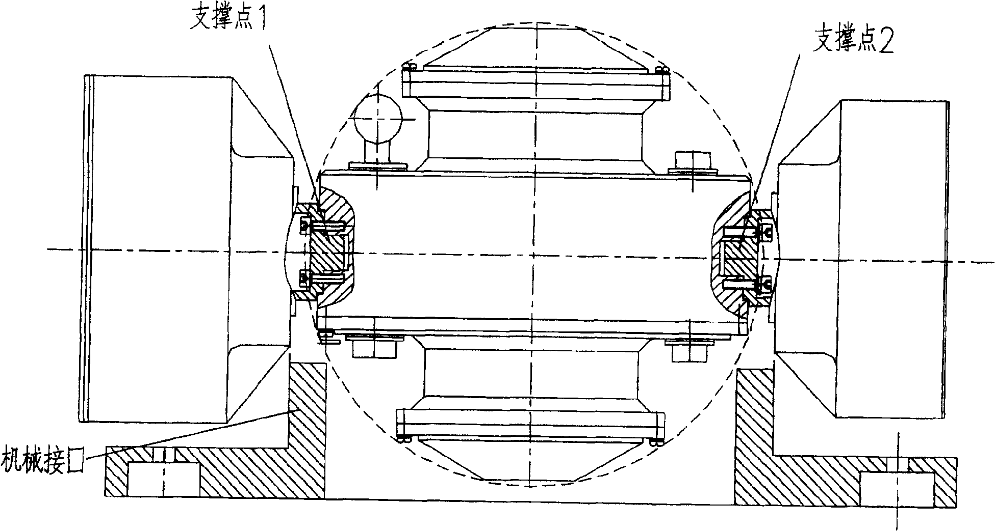
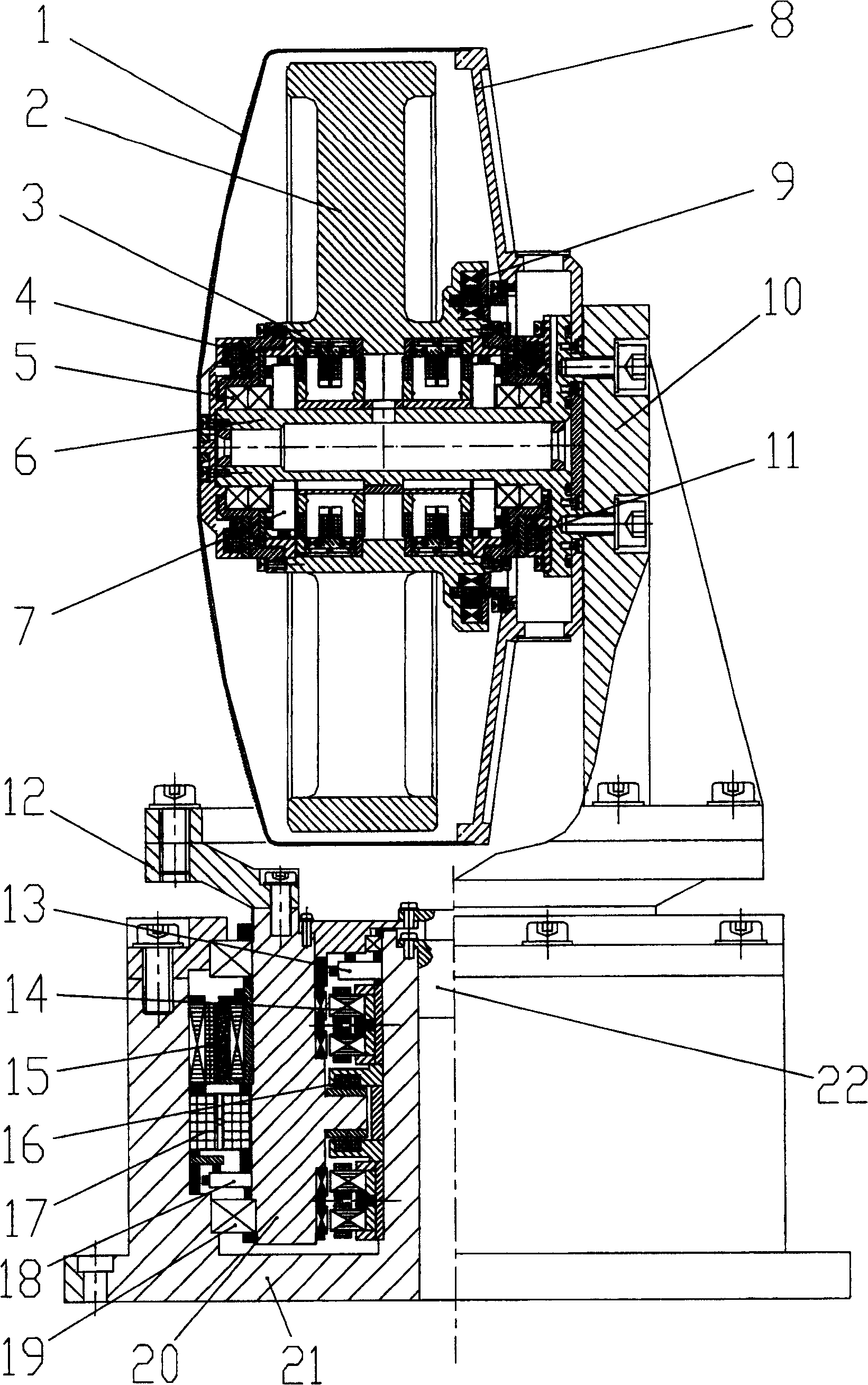
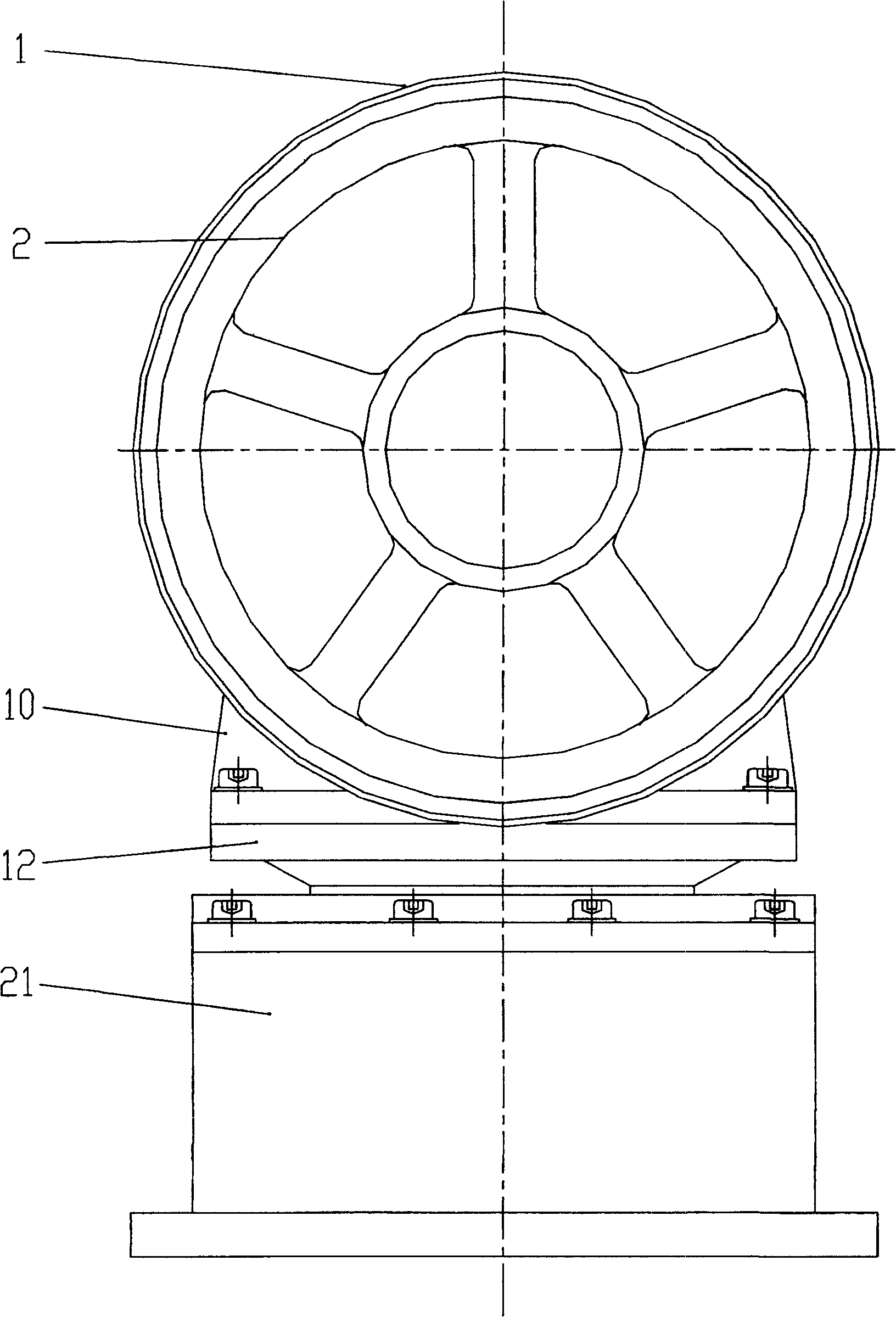
[0025] like figure 2, the present invention is mainly composed of a magnetic levitation rotor system and a magnetic levitation frame system. 6. Rotor system radial / axial integrated displacement sensor 7, rotor system base 8, drive motor 9, rotor system connector 10, right axial magnetic bearing 11, of which gyro rotor 2, radial magnetic bearing 3 rotor parts , drive motor 9 rotor parts, left axial magnetic bearing 4 rotor parts, right axial magnetic bearing 11 rotor parts form the rotor assembly of the magnetic levitation rotor system, and the rest is the stator assembly, and the radial magnetic bearing and the rotor assembly are connected between the stator assembly and the rotor assembly The axial magnetic bearing realizes stable suspension without mechanical contact. The radial magnetic bearing 3 is located in the middle of the magnetic levitation rotor system, and its stator part is installed on the shaft seat 6. The rotor part is connected with the gyro rotor 2. Outward...


PUM


Abstract

A fully non-contact single-frame magnetic- levitation torque-controlling gyro is composed of magnetically levitated frame system and magnetically levitated rotor system. Said magnetically levitated frame system consists of frame jointer, protecting bearing, mandrel, torque motor, angular position sensor, radial and axial magnetic bearings, integrated radial / axial displacement sensor, electrically conductive slide ring and base. Said magnetically levitated rotor system comprises gyro rotor, axle holder, axial and radial magnetic bearings, integrated radial / axial displacement sensor, protecting bearing, drive motor, sealing cover, base and jointer.

Description

technical field [0001] The invention relates to a completely non-contact single-frame magnetic levitation control moment gyroscope, which can be used for attitude control of large spacecraft such as space stations or small spacecraft such as agile maneuvering satellites. Background technique [0002] Modern satellite platforms or small spacecraft used in earth observation or scientific research have higher and higher requirements for stability and flexibility of maneuvering at large angles. Satellites that can maneuver at large angles can improve the efficiency and quality of Earth observation. The single-frame control moment gyro is one of the main actuators used for attitude control of spacecraft. The existing single-frame control moment gyroscope, the gyroscope rotor system and the frame system are all supported by mechanical bearings. Due to the wear of the mechanical bearings, there are still many restrictions on the speed and service life of the rotor system. At the s...

Claims


Application Information

Patent Timeline
Patent Type & Authority Patents(China)
IPC IPC(8): G01C19/24B64G1/28
Inventor 房建成叶全红孙津济韩邦成刘刚魏彤
Owner BEIHANG UNIV
Why Eureka
Try Eureka