Air conditioner

An air conditioning and refrigerant technology, applied in the direction of reversible cycle compressors, compressors, damage protection, etc., can solve the problems of refrigerant noise, refrigerant speed reduction, and increased pipe diameter, etc., to achieve high reliability, Effects of shorter defrosting time and safe energization

Inactive Publication Date: 2008-12-03
PANASONIC CORP
View PDF10 Cites 0 Cited by
  • Summary
  • Abstract
  • Description
  • Claims
  • Application Information

AI Technical Summary

Problems solved by technology

[0012] Therefore, this refrigeration cycle requires four 2-way valves, thus providing a complex and expensive way
[0013] In addition, since the refrigerant used for defrosting and the refrigerant that has dissipated heat in the indoor heat exchanger 110 merge, if the pressure of the refrigerant at the junction is higher than the pressure of the refrigerant used for defrosting, the refrigerant flows To the outdoor heat exchanger 103, if the opposite happens, the refrigerant will flow to the indoor side, and it may not be possible to perform defrosting operation while heating.
[0014] In addition, since the refrigerant used for defrosting merges with the refrigerant that dissipates heat in the indoor heat exchanger 110, refrigerant noise (refrigerant noise) is likely to be generated. In order to solve the above-mentioned pressure balance problem and refrigerant noise problem, sometimes it is necessary to set up the refrigerant combiner
[0015] In addition, since the amount of refrigerant circulation at the junction increases and the pressure loss increases, the diameter of the pipe needs to be increased as a countermeasure, and there is also a structural problem of increasing the size of the heater.
In addition, when the discharged heated refrigerant flows into a pipe with an enlarged pipe diameter, the speed of the discharged gas refrigerant decreases, and sufficient defrosting capability cannot be ensured, and frost may remain.
[0016] In addition, when operating in a refrigeration circuit, the inside of the piping of the refrigerant heater 104 is stabilized by the low-pressure refrigerant, and the temperature of the refrigerant heater 104 is lowered. 108 When the refrigerant leaks due to a fault, condensation will occur on the refrigerant heater, which sometimes causes problems in the reliability and safety of the refrigerant heater

Method used


Image

  • Air conditioner
  • Air conditioner
  • Air conditioner

Examples


Embodiment approach 1

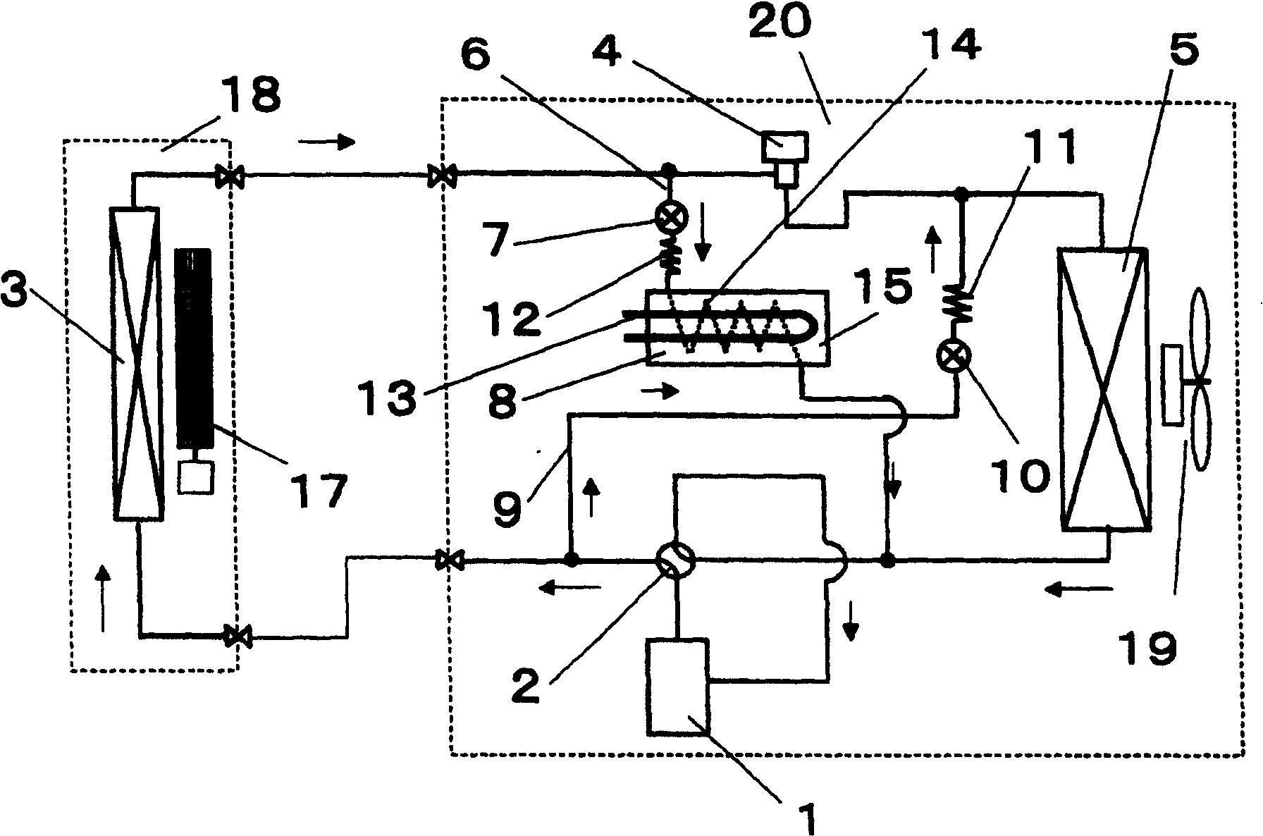
[0059] figure 1 It is a block diagram showing the air-conditioning apparatus according to Embodiment 1 of the present invention.

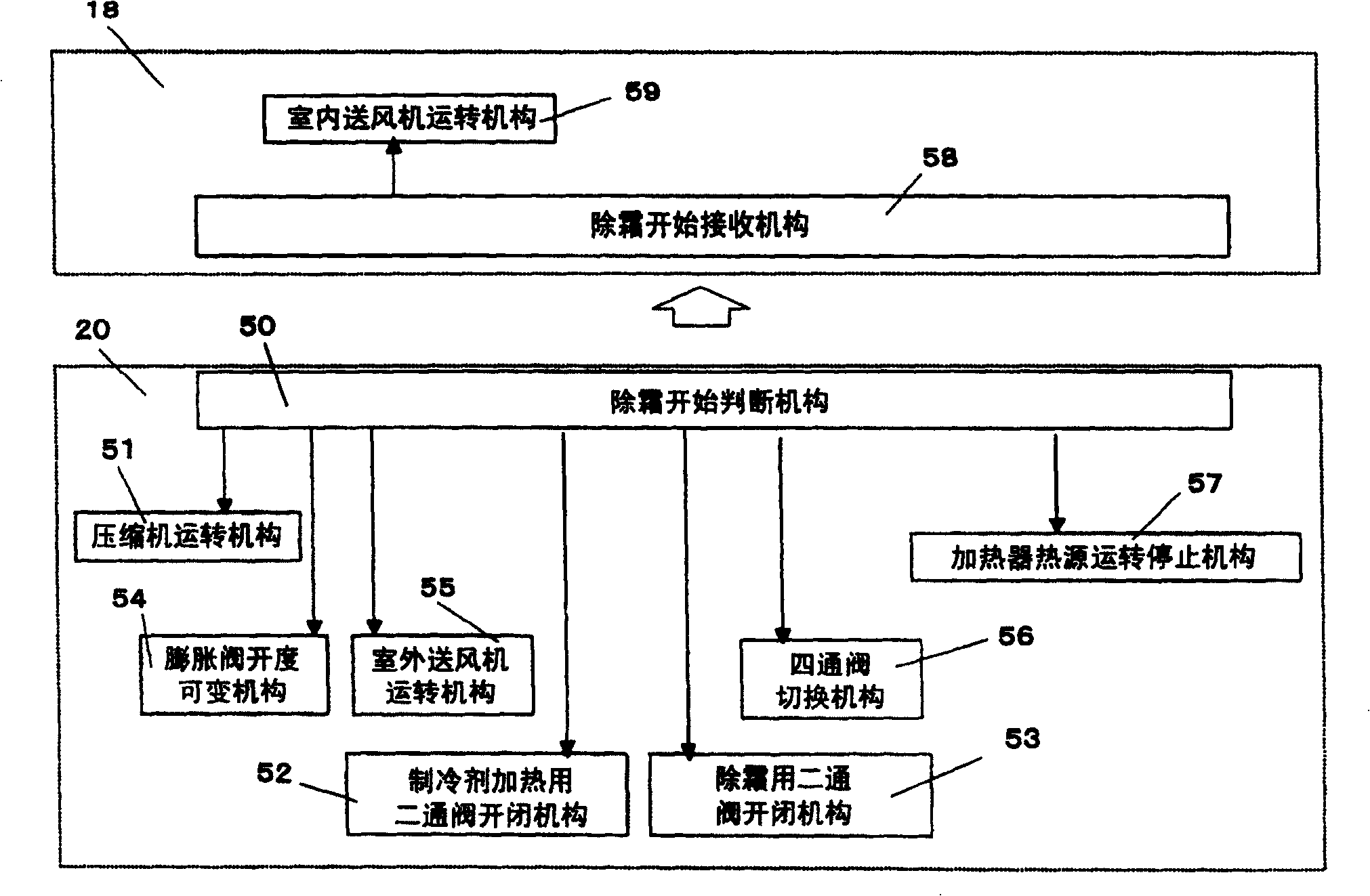
[0060] exist figure 1 Among them, the outdoor unit 20 includes a compressor 1 , a four-way valve 2 , a pressure reducer 4 , an outdoor heat exchanger 5 , and an outdoor fan 19 . The pressure reducer 4 here can also be an electromagnetic expansion valve. On the other hand, the indoor unit 18 includes the indoor heat exchanger 3 and the indoor blower 17 .

[0061] In addition, the outdoor unit 20 is provided with a first bypass circuit 6 and a second bypass circuit 9 . The first bypass circuit 6 connects the piping between the indoor heat exchanger 3 and the pressure reducer 4, and the piping between the four-way valve 2 and the outdoor heat exchanger 5, and has a two-way valve 7 for refrigerant heating, a refrigerant Heater 8. Further, the refrigerant heater 8 includes a pressure reducer 12 for refrigerant heating, a refrigerant heating heat ...

Embodiment approach 2

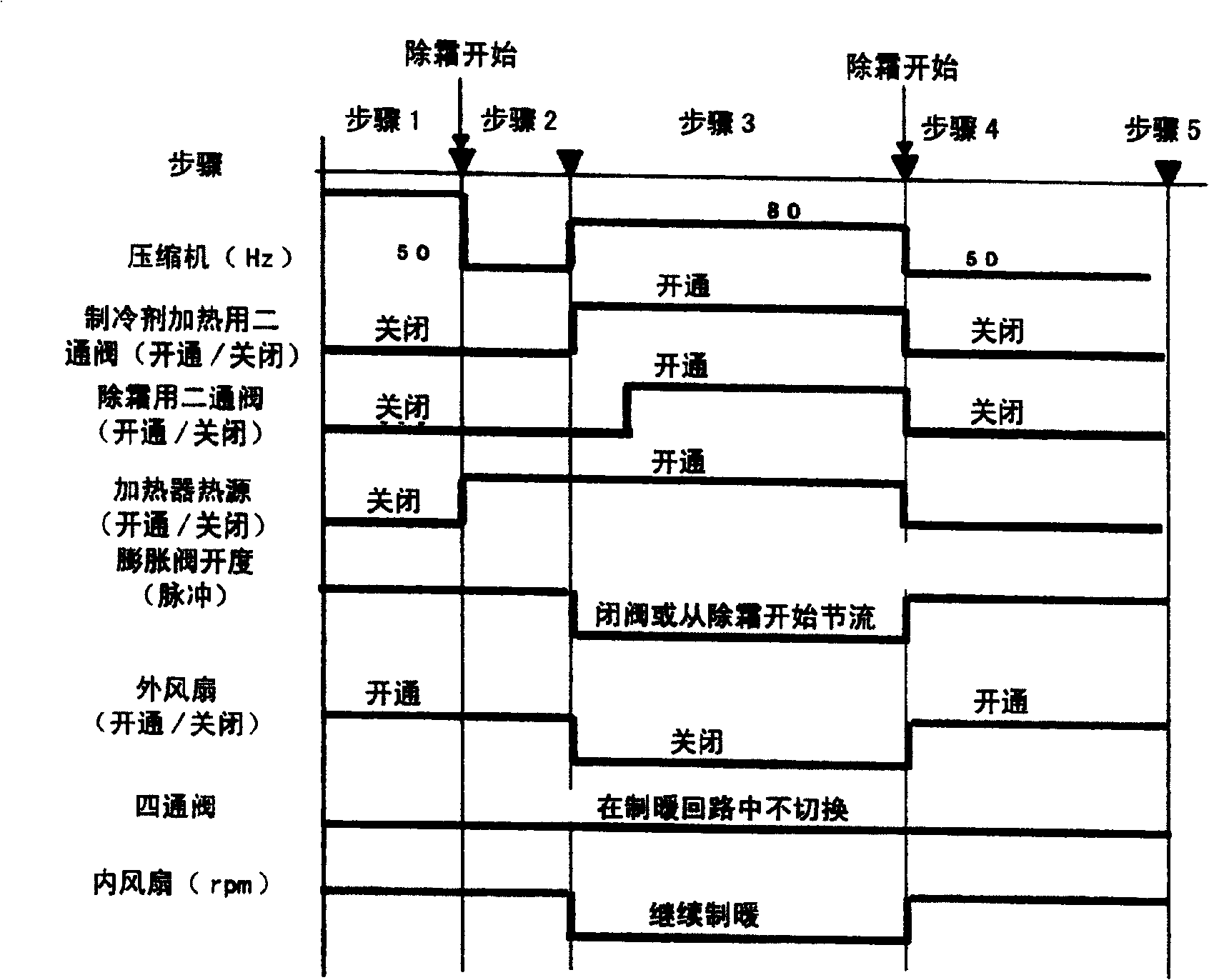
[0075] Figure 4 It is a time chart when the control of Embodiment 2 of this invention operates, and the structural diagram and control block diagram of an air-conditioning apparatus are the same as Embodiment 1 mentioned above.

[0076] Such as Figure 4 As shown, when it is judged to start defrosting, the heating operation by the heat pump in step 1 is performed, and the preparatory operation before turning on the refrigerant heating heat source 13 of the refrigerant heater 8 in step 2 is performed. In this preparatory operation, the frequency of the compressor 1 is reduced by changing the current control value in a decreasing direction to reduce the integrated current value until the current capacity does not exceed the standard, and the refrigerant heating heat source 13 can be safely turned on.

[0077] Next, in step 3, the current control value is increased, and the refrigerant heating heat source 13 is turned on. In addition, the frequency of the compressor is then in...

Embodiment approach 3

[0080] Figure 5 It is a time chart when the control of Embodiment 3 of this invention operates, and the structural diagram and control block diagram of an air-conditioning apparatus are the same as Embodiment 1 mentioned above.

[0081] Such as Figure 5 As shown, when it is judged to start defrosting, the heating operation by the heat pump in step 1 is shifted to the heating operation by the refrigerant heating operation in step 2 .

[0082] First, the two-way valve 7 for refrigerant heating is opened to control in the opening direction, and the refrigerant heating heat source 13 is also turned on to perform the refrigerant heating operation. At this time, the pressure reducer 4 such as an expansion valve performs a closed operation or a nearly closed operation.

[0083] Therefore, most of the refrigerant condensed by the indoor heat exchanger 3 flows into the first bypass circuit 6, passes through the two-way valve 7 for refrigerant heating, the pressure reducer 12 for re...


PUM


Abstract

To provide an air conditioner carrying out defrosting operation while continuing heating operation. This air conditioner comprises a first bypass circuit connecting the suction side of a compressor between an indoor heat exchanger and a decompressor of a heat pump type refrigeration cycle, the first bypass circuit including a two-way valve and a refrigerant heater; and a second bypass circuit connecting a part between a four-way valve connected to the refrigeration cycle and the indoor heat exchanger to a part between the decompressor and an outdoor heat exchanger, the second bypass circuit is provided with two-way valve. When defrosting the outdoor heat exchanger is performed, the two-way valve of the first bypass circuit and the two-way valve of the second bypass circuit are opened to guide current to the refrigerant heater for heat storage prior to the defrosting operation, and the defrosting operation is performed while continuing heating.

Description

technical field [0001] The present invention relates to an air conditioner capable of performing a defrosting operation for removing frost adhering to an outdoor heat exchanger while continuing heating during heating operation by heat pump operation. Background technique [0002] Conventionally, such a heat pump air conditioner generally employs a defrosting method in which a four-way valve is switched and the refrigerant in the refrigeration cycle flows in the opposite direction in order to remove frost adhering to the outdoor heat exchanger during heating. That is, in the defrosting operation, the refrigerant flows in the same direction as that during cooling, and high-temperature and high-pressure refrigerant flows through the outdoor heat exchanger to melt frost adhering to the heat exchanger. [0003] In this defrosting method, since the indoor heat exchanger becomes an evaporator during defrosting, there is a basic problem that the temperature in the room is lowered du...

Claims


Application Information

Patent Timeline
Patent Type & Authority Patents(China)
IPC IPC(8): F25B47/02F25B13/00
Inventor 西原义和后藤英二浅田德哉中村康裕太田雅也吉椿纪史藤社辉夫西川和宏荒岛博
Owner PANASONIC CORP
Why Eureka
Try Eureka