
Optical control nano second electric igniter

An electric ignition device and nanosecond technology, which can be used in weapon accessories, fuzes, offensive equipment, etc., can solve problems such as immature bonding, high cost of lasers, and low output power of laser diodes, so as to avoid electrostatic discharge and improve shooting Performance, responsiveness and effects

Inactive Publication Date: 2009-01-21
XIAN UNIV OF TECH
View PDF4 Cites 1 Cited by
  • Summary
  • Abstract
  • Description
  • Claims
  • Application Information

AI Technical Summary

Problems solved by technology

(6) It avoids the impact of ignition tube damage, detachment, and the distance of detachment from the drug package on the ignition performance, and improves the shooting safety. However, laser ignition technology also has problems such as high cost of lasers, low output power of laser diodes, and ) The shortcomings of the optical fiber's load capacity are not strong enough, and the bonding force is not mature enough, which hinders its wide application

Method used


Image

  • Optical control nano second electric igniter
  • Optical control nano second electric igniter
  • Optical control nano second electric igniter

Examples


Embodiment Construction

[0020] The present invention will be described in detail below in conjunction with the accompanying drawings and specific implementation formulas.

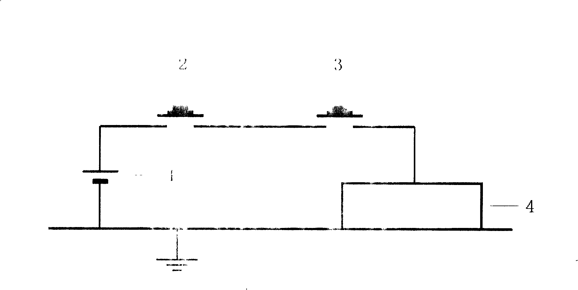
[0021] figure 1 What is provided is the circuit schematic diagram of the existing electric ignition device-unipolar ignition system. The electric ignition device 4 is connected in series with the ignition switch 3 and the safety switch 2, and forms a circuit with the ignition power supply 1. Considerable currents are induced on accessories such as live wires. Although the single-pole shielded wire can be used to design the single-pole ignition system to be safe and reliable in the specified radiation environment by adopting shielding and filtering methods, the ignition switch is still prone to high currents induced by other forms of electromagnetic interference. Voltage breakdown, causing false emission.

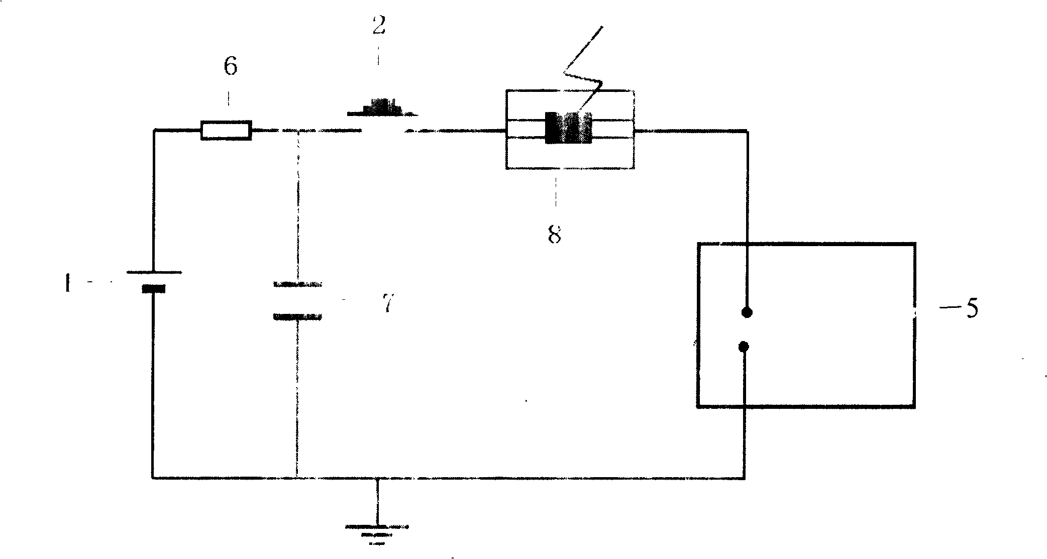
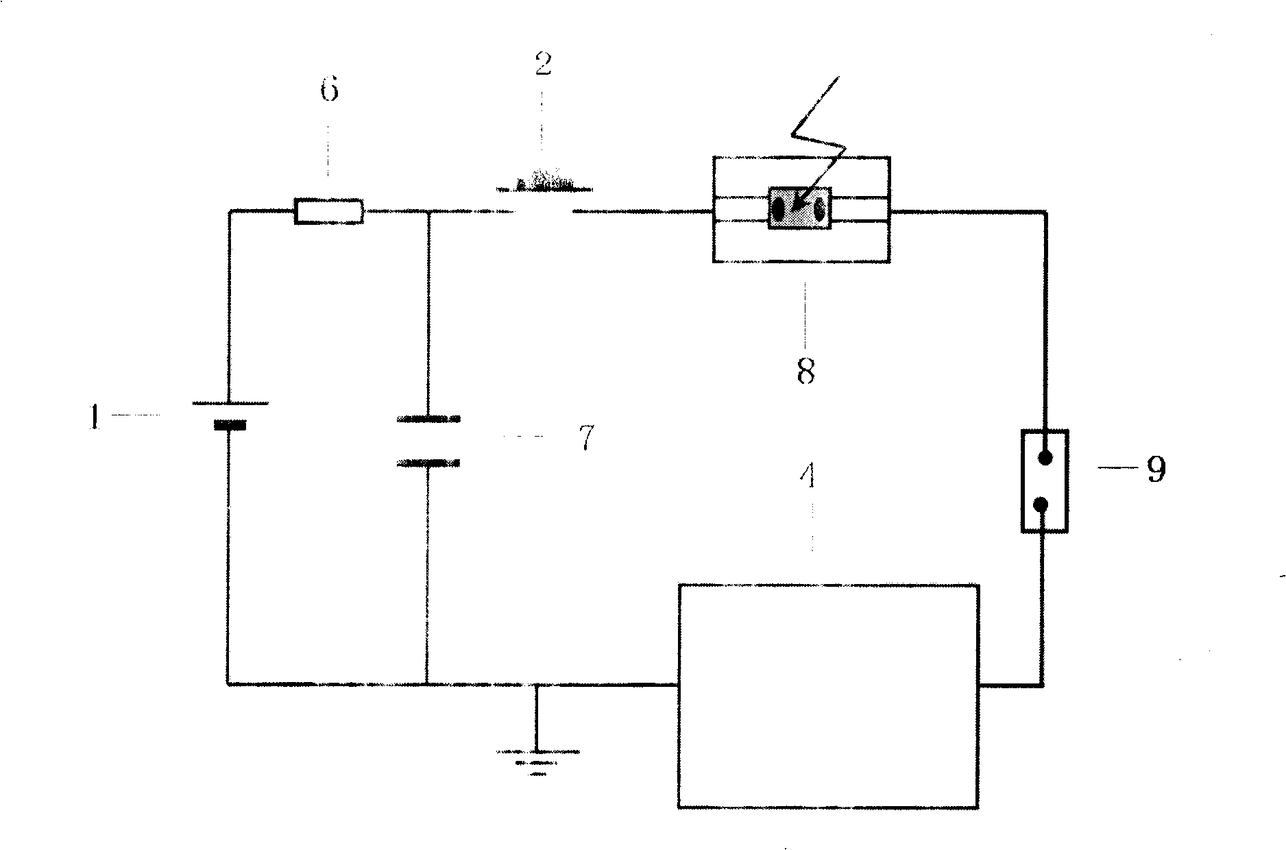
[0022] The light-controlled nanosecond electric ignition device of the present invention is composed of a dielectric gap ele...


PUM


Abstract

The optically controlled nano-second electric igniter includes one serially connected circuit comprising a medium gap electric igniter, a very fast optical conducting switch and a safety switch and one energy accumulating element with negative pole connected to ground and constituting one closed loop together with the serially connected circuit. The optically controlled nano-second electric igniter of the present invention is superior to available electric igniter and laser igniter, and has the advantages of resisting electromagnetic radiation interference and static electricity, high sensitivity and fast response speed.

Description

technical field [0001] The invention is a new application of a photoconductive switch in the military field, relates to an ignition device, in particular to a light-controlled nanosecond electric ignition device composed of a laser, a photoconductive switch and a dielectric gap. Background technique [0002] An electric ignition device is a pyrotechnic device that detonates through electric energy. It has sensitive sensitivity, reliable function, low power input and fast response, and can detonate explosive equipment including pyrotechnic devices, so it is widely used in current artillery, missiles and other weapons and equipment and many civilian blasting systems. However, the electric ignition device is very sensitive, and may cause heating to the priming charge due to various electrical energy inputs of any frequency, causing it to detonate; it may also cause the ignition circuit switch to be activated prematurely to cause detonation. There are security risks. In the mo...

Claims


Application Information

Patent Timeline
Patent Type & Authority Patents(China)
IPC IPC(8): F42C19/12
Inventor 施卫侯磊徐鸣施志贵刘娟文贵印
Owner XIAN UNIV OF TECH
Learn More