
Cooling device with cooling fan

A cooling fan and cooling device technology, applied to the cooling of the engine, engine components, machines/engines, etc., can solve the problems of increasing the driving energy consumption of the cooling fan, increasing the capacity of the cooling fan, etc., so as to improve the cooling performance and suppress the ventilation resistance , to promote the effect of heat dissipation

Inactive Publication Date: 2009-02-18
HONDA MOTOR CO LTD
View PDF3 Cites 1 Cited by
  • Summary
  • Abstract
  • Description
  • Claims
  • Application Information

AI Technical Summary

Problems solved by technology

[0003] Here, in the above-mentioned prior art, in the cooling wind at the windward position of the cooling fan after passing through the radiator core, there is an airflow in a direction other than the rotation centerline of the cooling fan (hereinafter referred to as "turbulent flow") , which includes the rotating part affected by the rotating cooling fan, and the radially outward part affected by the radially outward flow of exhaust air, etc. Therefore, the cooling air passing through the radiator core cannot be cooled by the cooling fan Inhalation is smooth, and as a result, in order to ensure the air volume of the cooling air passing through the radiator core, the capacity of the cooling fan must be increased in consideration of the above-mentioned turbulence of the air flow, thereby increasing the driving energy consumption of the cooling fan

Method used


Image

  • Cooling device with cooling fan
  • Cooling device with cooling fan
  • Cooling device with cooling fan

Examples


Embodiment Construction

[0025] Below, with reference to accompanying drawings 1 to Figure 5 Embodiments of the present invention will be described.

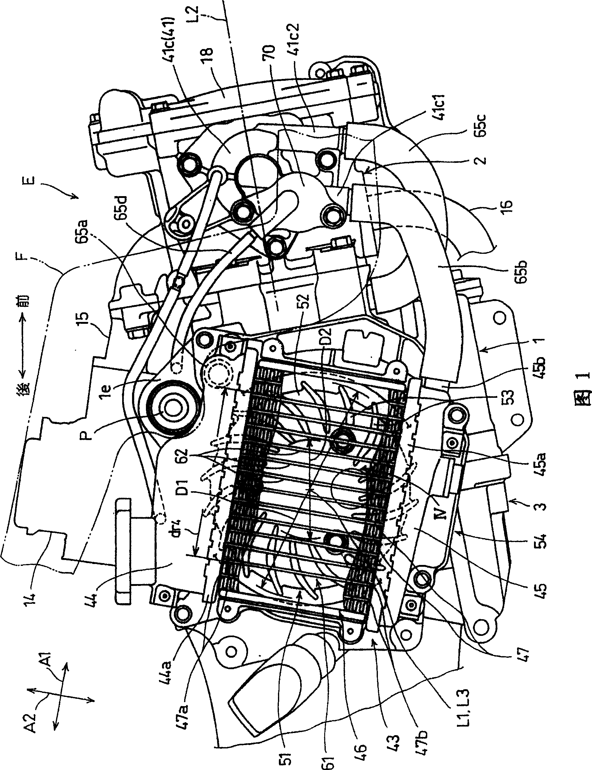
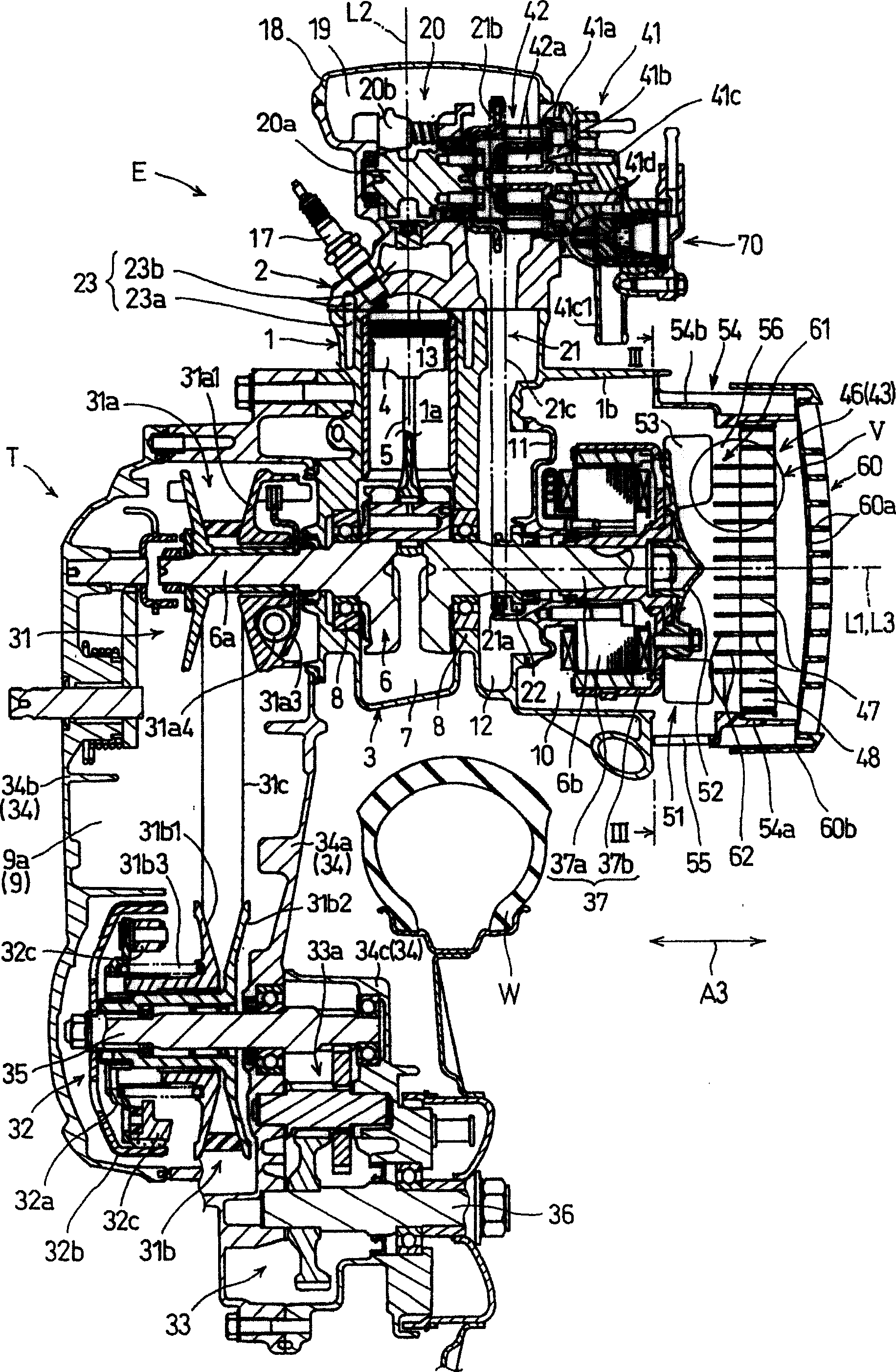
[0026] See Figure 1 and figure 2 , the cooling device of the present invention is disposed on a water-cooled internal combustion engine E in a scooter-type motorcycle as a vehicle. The single-cylinder internal combustion engine E together with the transmission T constitutes a power assembly for transmitting the power of the internal combustion engine E to the rear wheels W as drive wheels. The power unit is supported on a pair of supported parts (shown as a supported part 1e formed on the cylinder 1 in FIG. 1 ), and can swing up and down centered on a pivot P held on the body frame F, The pair of supported portions are formed integrally with the cylinder 1 of the internal combustion engine E and the first case portion 34a of the transmission T, respectively.

[0027] The internal combustion engine E is an overhead camshaft type single-cylinder four-...


PUM


Abstract

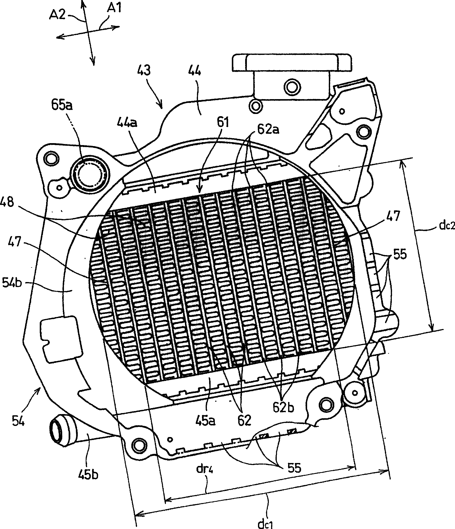
To provide a cooling device decreasing turbulence of airflow of cooling air to increase the volume of the cooling air, and thereby improving the cooling performance of a radiator and reducing drive energy of a cooling fan.The cooling device of water cooled internal combustion engine E comprises: the radiator having a radiator core in which cooling water radiating heat into the cooling air flows; the cooling fan disposed downstream the radiator core to face the radiator core in a rotation center direction A3; and straightening plates disposed between the radiator core and the cooling fan in the rotation center line direction A3. The straightening plates guide the cooling air just after passing through the radiator core along the rotation center line direction A3 up to just in front of a rotation track of an upstream edges of blades of the cooling fan. Each of the straightening plates is disposed so that, in immediate downstream of a downstream end of a heat transmission tube of the radiator core, the upstream end is opposite to and is arranged along the downstream edge in the rotation center line direction A3.

Description

technical field [0001] The present invention relates to a cooling device having a radiator core and a suction cooling fan in which a fluid that radiates heat to the cooling air flows through the radiator core and the suction cooling fan generates the cooling wind, the cooling device is, for example, used Cooling device for water-cooled internal combustion engines. Background technique [0002] A kind of radiator is disclosed by such as Japanese Patent Publication No. 2002-129960, and this radiator has radiator core, and this radiator is equipped with centrifugal cooling fan at the downwind place of radiator core, and the cooling that cooling fan produces The cooling water cooled by the wind flows through the above-mentioned radiator core. In the radiator, the cooling air is introduced through the louver under the action of the cooling fan and passes through the radiator core, thereby cooling the cooling water flowing through the radiator core. The cooling air passing throu...

Claims


Application Information

Patent Timeline
Patent Type & Authority Patents(China)
IPC IPC(8): F01P11/00
Inventor 五十岚和则
Owner HONDA MOTOR CO LTD
Learn More