
Display device

A standby circuit and low power consumption technology, which is applied to color TV components, TV system components, TVs, etc., can solve the problem of high standby power consumption, achieve low power consumption, improve efficiency, and reduce costs

Inactive Publication Date: 2009-03-04
SHENZHEN TCL NEW-TECH CO LTD
View PDF7 Cites 0 Cited by
  • Summary
  • Abstract
  • Description
  • Claims
  • Application Information

AI Technical Summary

Problems solved by technology

[0004] Therefore, the purpose of the present invention is to provide a low-cost, low-power standby circuit, which can effectively solve the problem of large standby power consumption, and make the TV set always maintain a low standby power consumption working state

Method used


Image

  • Display device
  • Display device
  • Display device

Examples


Embodiment Construction

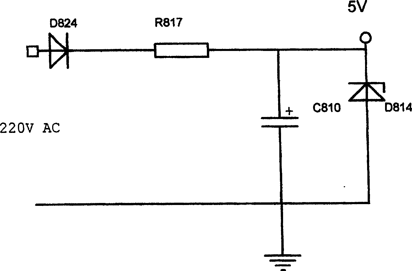
[0021] figure 1 Shown, the stand-by circuit of the present invention is by 220V directly through the rectifier diode, resistance, electric capacity, 5V zener diode forms the low current power supply circuit; 220V AC is directly through D824, R817, C810, D814 rectification; current supply, reducing the power consumption of the standby circuit.

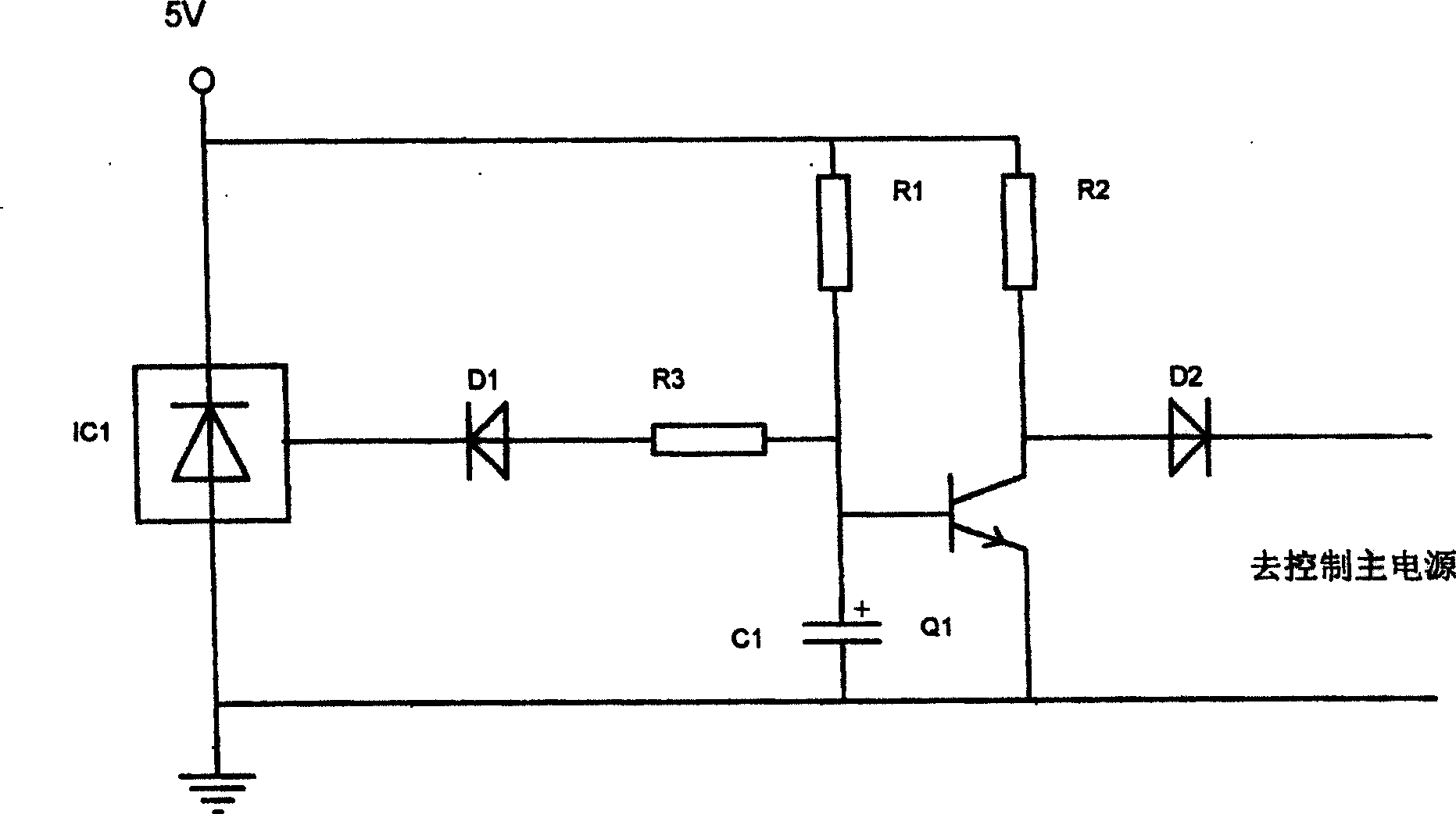
[0022] The specific standby circuit consists of two parts: the receiving end and the transmitting end. For the receiving end, its control circuit is as follows: figure 2 shown. IC1 is the infrared receiving head. When there is no signal, Q1 is turned on by R1, D2 is cut off, and the main power supply does not work. When IC1 receives the signal, the charge on C1 is discharged through R3, D1, and IC1, and Q1 is cut off. D2 is turned on, and the main power supply works. Adjust the parameters of R3 and C1 (R3 and C1 are respectively connected to the base of the triode Q1), and the infrared receiving head can be controlled to receive the ...


PUM


Abstract

The invention belongs to stand-by circuit of low power consumption for TV, which comprises low current supply circuit composed of a 220V rectification diode, a resistance, a capacitor, and a 5V voltage stabilizing diode, and infrared receiving tube, to monitor infrared remote control signal. This invention can allow TV keeps low consumption state.

Description

technical field [0001] The invention relates to a switch circuit of a TV set, in particular to a standby circuit capable of reducing power consumption of the TV set. Background technique [0002] During the development of TV sets, with the acceleration of the digitalization process, the CPU and DSP are basically used inside the TV set to form a chip for digitally processing TV signals, and the power consumption of the chip is increasing with the increase of its processing capacity. , so that its power consumption during standby is difficult to meet environmental protection requirements, especially for high-end TVs with multiple functions, the burden of standby power consumption is very heavy, and a second CPU is usually added to achieve the purpose of reducing standby power consumption . [0003] The increase of the CPU means the increase of the circuit and the increase of the cost, which bring a negative impact to the highly competitive TV market, and consumers often becom...

Claims


Application Information

Patent Timeline
Patent Type & Authority Patents(China)
IPC IPC(8): H04N5/63H04N5/74G02F1/13G03B21/00
Inventor 唐余敏
Owner SHENZHEN TCL NEW-TECH CO LTD
Features
  • Generate Ideas
  • Intellectual Property
  • Life Sciences
  • Materials
  • Tech Scout
  • Unparalleled Data Quality
  • Higher Quality Content
  • 60% Fewer Hallucinations
Learn More