Direct-driving three-freedom serial-parallel mixed precision positioning mechanism

A precision positioning and degree of freedom technology, applied in the direction of manipulators, instruments, metal processing, etc., can solve the problems of influence, difficulty in meeting the requirements of precision and work efficiency in the microelectronics industry, and long mechanical establishment time

Inactive Publication Date: 2009-04-15
HARBIN INST OF TECH
View PDF5 Cites 0 Cited by
  • Summary
  • Abstract
  • Description
  • Claims
  • Application Information

AI Technical Summary

Problems solved by technology

This type of device has the following disadvantages: 1) The motor must follow the movement of the worktable, which increases the motion inertia, which is not conducive to improving the movement speed and acceleration of the mechanism, and the mechanical establishment time is also longer, and it is affected by the cable following the movement of the motor
2) The traditional ball screw is limited by the transmission stiffness, the motion clearance of the transmission link and heat generation, and has reached its precision and speed limit. Due to the flexibility of the deceleration transmission link, its mechanism has a long stable time
Due to the above shortcomings, it is difficult for existing technologies to meet the precision and work efficiency requirements of the microelectronics industry for next-generation equipment

Method used


Image

  • Direct-driving three-freedom serial-parallel mixed precision positioning mechanism
  • Direct-driving three-freedom serial-parallel mixed precision positioning mechanism

Examples


Embodiment Construction

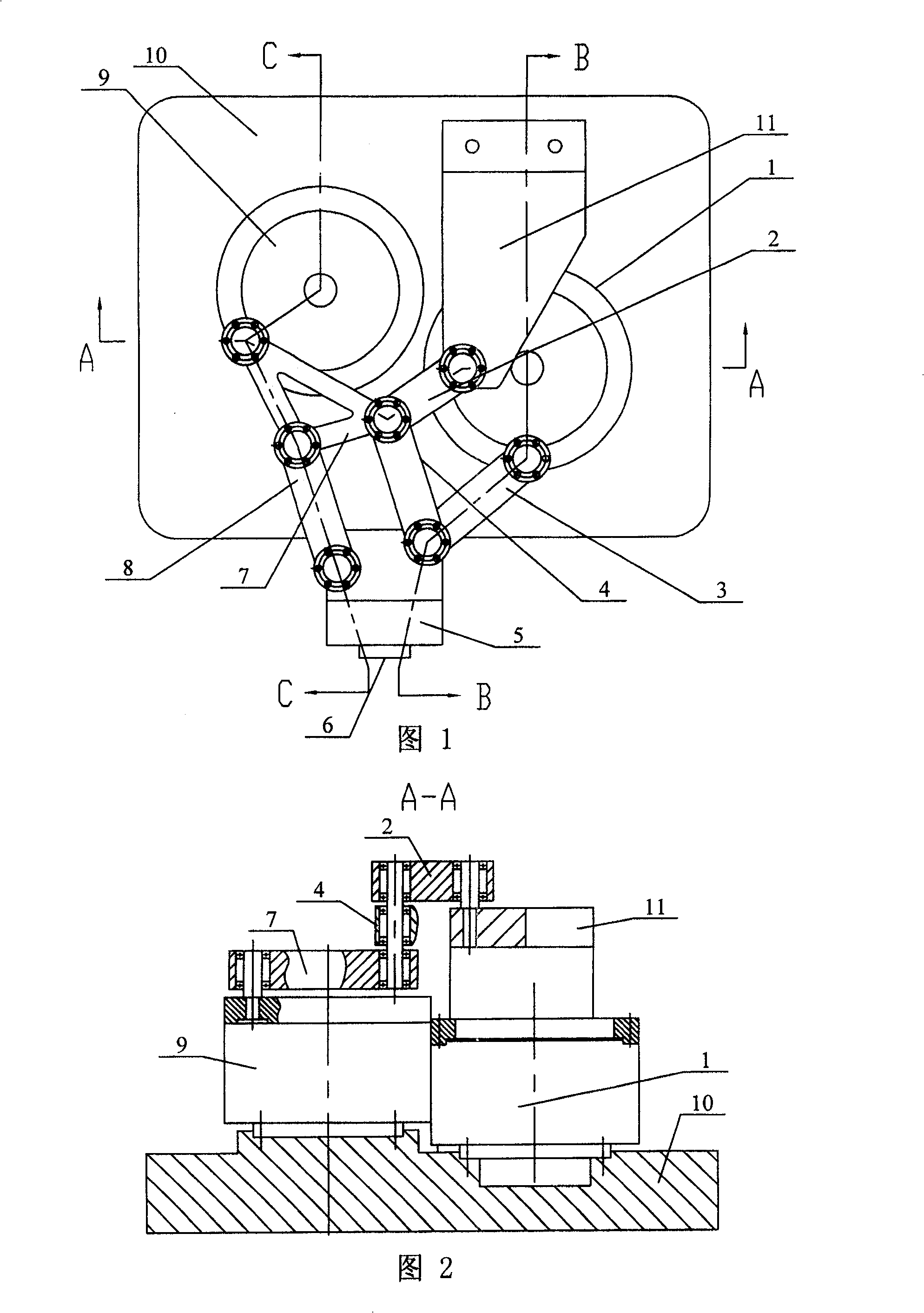
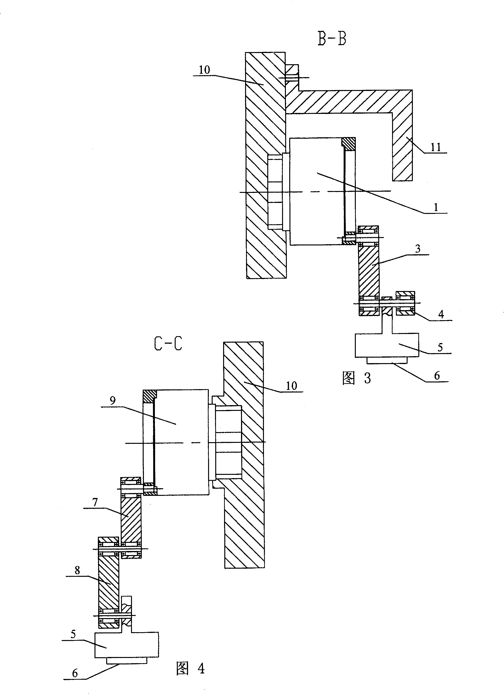
[0005] (see Fig. 1-Fig. 4) present embodiment is made up of No. 1 motor 1, No. 1 connecting rod 2, No. 2 connecting rod 3, No. 3 connecting rod 4, output module 5, linear motion module 6, No. 4 connecting rod 7, The fifth connecting rod 8, the second motor 9, the machine base 10, and the bent plate 11 are composed; the bent plate 11 is fixed on one side of the machine base 10, and the bases of the first motor 1 and the second motor 9 are respectively fixed on the machine base 10 Above, one end of the No. 1 connecting rod 2 is hinged to the curved plate 11, the other end of the No. 1 connecting rod 2 is hinged to one end of the No. 3 connecting rod 4 and No. 4 connecting rod 7, and one end of the No. The output end of No. 1 is hinged, the other end of No. 3 connecting rod 4, the other end of No. 2 connecting rod 3, and the output module 5 are hinged sequentially from top to bottom, and the other end of No. 4 connecting rod 7 is connected to the output end of No. 2 motor 9 Hinge...


PUM


Abstract

The positioning mechanism includes following parts ad connections: bent plate is fixed on a side of machine foundation, base of No.1 motor and base of No.2 motor are fixed on the foundation; one end of No.1 connecting rod is hinge-jointed to bent plate, and another end of No.1 connecting rod is connected to one end of No.3 and No.4 connecting rods respectively; one end of No.2 connecting rod is hinge-jointed to output end of No.1 motor, another ends of No.3 and No.2 connecting rods are hinge-jointed to output module from upper to lower respectively. The invention also contains No.5 connecting rod, and other connections etc. Rectilinear motion module is fixed to output module. Advantages are: compact structure, high positioning accuracy, and good dynamic performance.

Description

Technical field: [0001] The invention relates to a novel precision positioning mechanism. Background technique: [0002] At present, with the rapid development of industries involving the interconnection of tiny devices (dimensions or pitches on the micron level) such as integrated circuits (ICs) and micro-electromechanical systems (MEMS), higher interconnection technologies such as wire bonding (Wire Bonding) have been proposed. requirements. It is required to further improve the motion accuracy, speed and acceleration of such systems, so as to further improve the integration, manufacturing quality and production efficiency of microsystems and microdevices such as IC and MEMS. Existing systems of this type, such as die bonders and wire bonders, use two degrees of freedom in the form of a motor-screw-nut mechanism, a horizontal movement table in the form of a rectangular coordinate, and a vertical movement in the form of a rotary movement. workbench. This type of device h...

Claims


Application Information

Patent Timeline
Patent Type & Authority Patents(China)
IPC IPC(8): B23Q41/04B23Q7/14B25J1/02B25J1/12B25J3/02G12B5/00
Inventor 孙立宁丁庆勇刘延杰祝宇虹刘新宇
Owner HARBIN INST OF TECH
Why Eureka
Try Eureka