
Mobile communication base station plane multiware beam antenna

A technology of mobile communication base station and multi-beam antenna, which is applied in the direction of separately powered antenna array, antenna, antenna array, etc., can solve the problems of lack of space angle diversity capability and interference suppression capability, achieve low profile, simplify volume, realize and The effective effect of performance expansion

Inactive Publication Date: 2009-05-13
ZTE CORP
View PDF4 Cites 0 Cited by
  • Summary
  • Abstract
  • Description
  • Claims
  • Application Information

AI Technical Summary

Problems solved by technology

[0004] The main purpose of the present invention is to provide a mobile communication base station planar multi-beam antenna, solve the problem of realizing the base station multi-beam antenna in the mobile communication smart antenna, provide a smart antenna system that is easy to implement in engineering and has a relatively high performance and price, and overcomes existing problems. The mobile communication base station antenna adopts a fixed wide beam, which has no disadvantages of spatial angle diversity and interference suppression, and effectively improves the system capacity of mobile communication

Method used


Image

  • Mobile communication base station plane multiware beam antenna
  • Mobile communication base station plane multiware beam antenna
  • Mobile communication base station plane multiware beam antenna

Examples


Embodiment Construction

[0036] Below in conjunction with accompanying drawing and specific embodiment the present invention is described in further detail:

[0037] In a preferred embodiment of the present invention, the main function of the multi-beam antenna is to uniformly generate four narrow beams within an azimuth angle of 120°, the horizontal beam width is about 30°, and the beam pointing positions are respectively ±15°. °, ±45°, vertical beam width is about 12°, zero point fading ≥-30dB, antenna gain ≥17dBi.

[0038] The multi-beam antenna of this embodiment mainly consists of the following four modules:

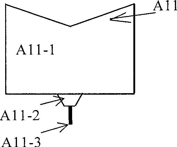
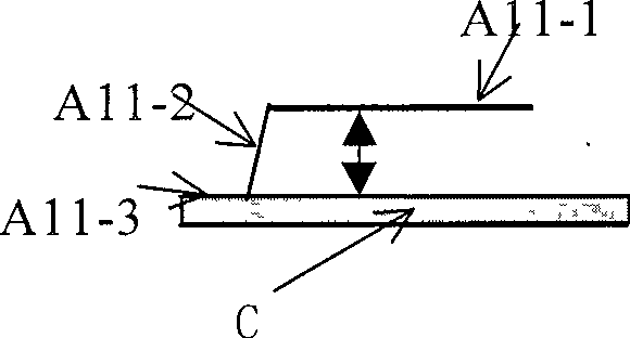
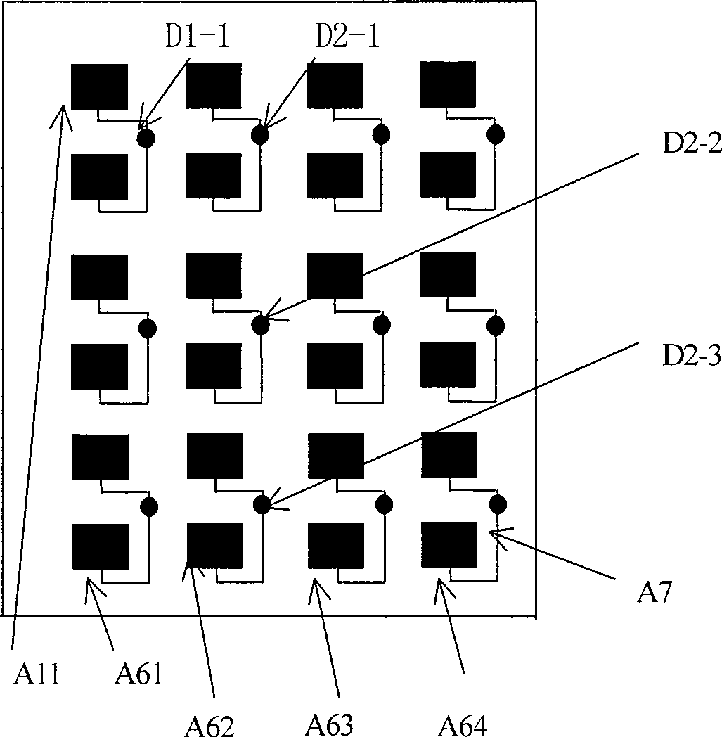
[0039] see figure 1 , figure 2 image 3 , the broadband planar antenna array A is composed of 4 sub-linear arrays A1, A2, A3, A4 and feeders, and each sub-linear array is composed of 6 antenna elements A11, so that the antenna array A consists of 6 rows and 4 columns with a total of 24 antenna elements , its working principle is based on this 6×4 space array structure to collect space ...


PUM


Abstract

The antenna is composed of at least aerial array, beam-forming network of wide band Bulter, Chebyshev weighting network, metal base plate, circuit of power synthesis and decomposition. The aerial array is positioned on the metal base plate. Output of aerial array is connected to the said beam-forming network and the weighting network. The circuit of power synthesis and decomposition is connected to the aerial array and positioned on back surface of metal base plate. The aerial array possesses particular radiation structure and special current feeding system. In the invention, air microstrip antenna is as basic radiation source, and technique of planar array antenna, weighted amplitude and beam-forming network of wide band Bulter are adopted. Thus, the multi-beam antenna possesses features of small size, low profile, wideband and high efficiency. The invention simplifies size and structure so as to bring resultful realization for implementing aerial array and expanding performances.

Description

Technical field: [0001] The present invention relates to a kind of miniaturization, wide frequency band, medium-high gain planar multi-beam antenna, relate in particular to the structure of antenna unit and array on a kind of base station intelligent antenna product, especially relate to GSM (GlobalSystem for Mobile communications, global digital mobile telephone system) Base station multi-beam antenna with low sidelobe and main beam isolation in mobile communication environment. Background technique: [0002] In mobile communication systems (such as GSM, CDMA (Code Division Multiple Access) or PHS (Personal Handheld System), the base station antenna adopts smart antenna technology to realize spatial filtering (ie SDMA), which can effectively overcome multipath effects and reduce inter-symbol Interference, suppress co-channel interference, improve carrier-to-interference ratio, thereby significantly improving system capacity. Because of this, smart antenna technology (also k...

Claims


Application Information

Patent Timeline
Patent Type & Authority Patents(China)
IPC IPC(8): H01Q21/00H01Q21/06
Inventor 彭宏利谢玉堂
Owner ZTE CORP
Learn More