Emusified coking-slurry cyclone burner

A technology of cyclone combustion and coke slurry, which is applied in the direction of burners, combustion chambers, combustion methods, etc., can solve the problems of failing to reach the ash melting point of emulsified coke slurry ash slag, inability to liquefy emulsified coke slurry ash slag, and complex structure of the combustion chamber , to achieve the effect of solving the problem of fire and embers, reducing the temperature and reducing the formation of nitrogen oxides

Inactive Publication Date: 2009-06-17
GUANGZHOU DEVOTION THERMAL TECH
View PDF8 Cites 0 Cited by
  • Summary
  • Abstract
  • Description
  • Claims
  • Application Information

AI Technical Summary

Problems solved by technology

It can be seen from the above analysis that, firstly, the backfired coal-water slurry liquid slagging combustion furnace is not suitable for the combustion of emulsified coke slurry; secondly, the combustion chamber temperature of the backfired coal water slurry liquid slagging combustion furnace is still low The ash melting point of the emulsified coke slurry ash cannot be reached, and the emulsified coke slurry ash cannot be liquefied; finally, the combustion chamber structure of the reverse combustion type coal-water slurry liquid slagging combustion furnace is complicated, and the manufacturing cost is high

Method used


Image

  • Emusified coking-slurry cyclone burner
  • Emusified coking-slurry cyclone burner
  • Emusified coking-slurry cyclone burner

Examples


Embodiment 1

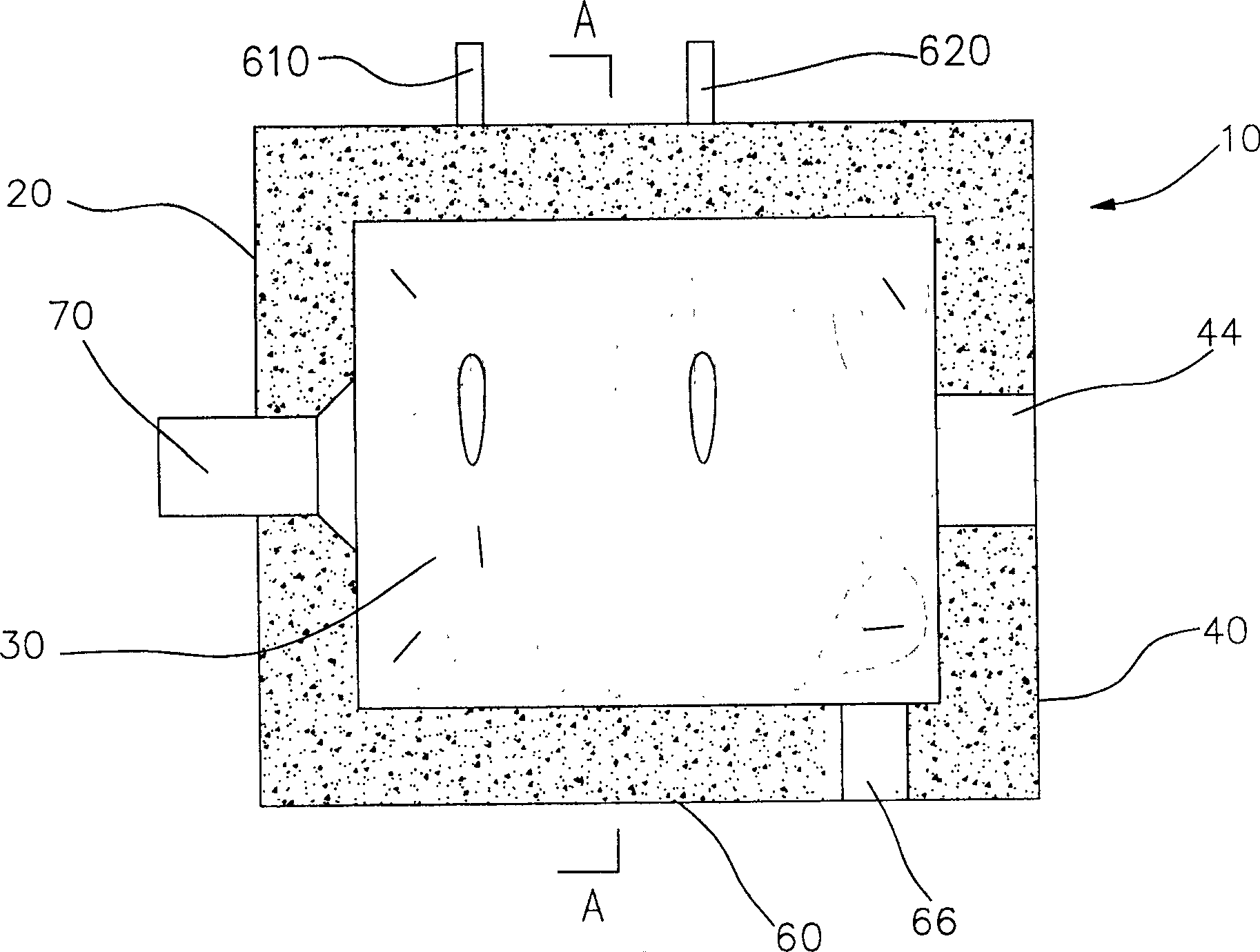
[0037] Please refer to figure 1 And Fig. 2, the emulsified coke slurry cyclone combustion device of the present invention includes a shell 10, an emulsified coke slurry burner 70, an oil burner and a gas burner (not shown).

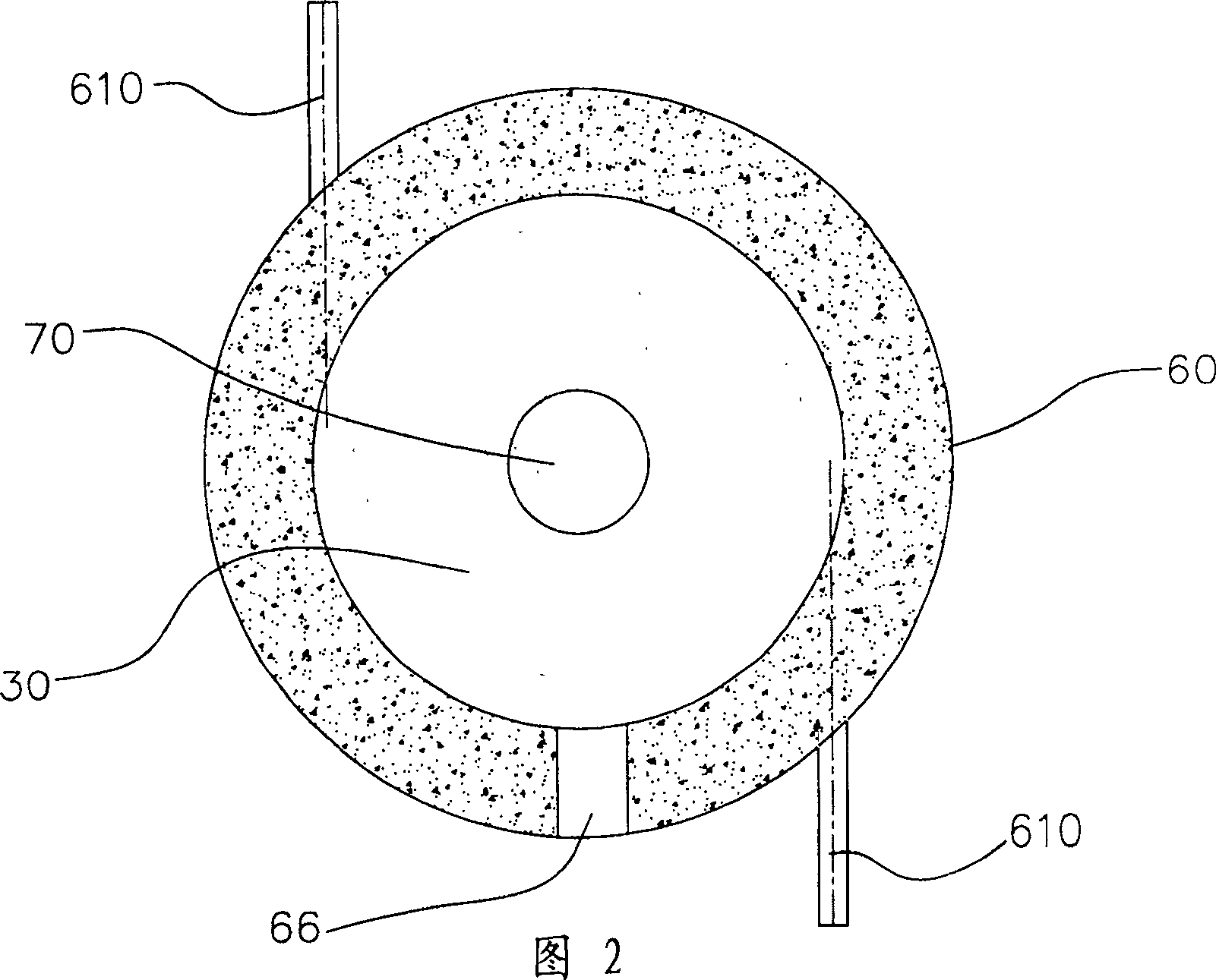
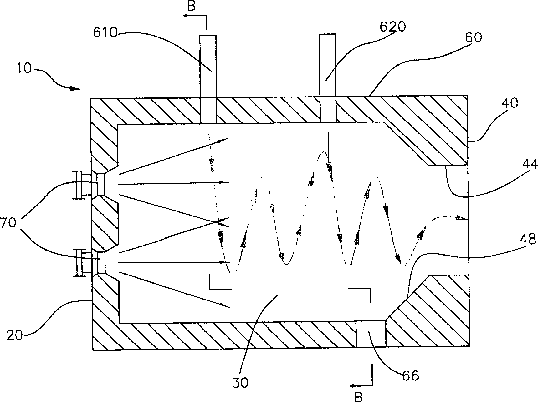
[0038] The housing 10 is surrounded by a front wall 20 , a rear wall 40 , and a side wall 60 . The casing 10 is cylindrical, and a cylindrical combustion space 30 is formed inside the casing 10 . The vertical distance between the inner wall of the rear end wall 40 and the inner wall of the front end wall 20 is three times the inner diameter of the combustion space 30 .

[0039] The front end wall 20 of the housing is uniformly provided with an emulsified coke burner 70, an oil burner and a gas burner, wherein the emulsified coke burner 70 is arranged at the center of the front end wall 20, and the oil burner and the gas burner are arranged at the emulsified Below the char slurry burner 70. The emulsified coke burner 70, the oil burner and the gas burne...

Embodiment 2

[0052] Please refer to image 3 and Figure 4 , this embodiment is similar to Embodiment 1, the difference is:

[0053] The opening area of ​​the liquid slag outlet 66 on the inner wall of the side wall 60 is approximately equal to one-twentieth of the cross-sectional area of ​​the combustion space 30 .

[0054] The vertical distance between the inner wall of the front end wall 20 and the inner wall of the rear end wall 40 is 1.5 times the meat diameter of the combustion space 30 .

[0055] The diameter of the outlet 44 is about half of the inner diameter of the combustion space 30 , and a conical transition chamber 48 is formed between the outlet 44 and the side wall 60 of the housing 10 . That is, a flared opening is formed on the rear end wall 40 .

[0056] There are four emulsified coke slurry burners 70, and the four emulsified coke slurry burners 70 are respectively installed on the front end wall 20, and are distributed at equal intervals on the circumference with th...

Embodiment 3

[0064] This embodiment is similar to Embodiment 1, the difference is:

[0065] The emulsified coke slurry cyclone combustion device is provided with two liquid slag outlets 66 of the same size distributed at intervals, and the opening area of ​​each liquid slag outlet 66 on the inner wall of the side wall 60 is approximately equal to one-thirtieth of the cross-sectional area of ​​the combustion space one.

[0066] The vertical distance between the inner wall of the rear end wall 40 and the inner wall of the front end wall 20 is 4 times the inner diameter of the combustion space 30 .

[0067] The wind speed of the tangential wind delivered to the combustion space 30 by each tangential wind inlet is 28 m / s. Three groups of tangential air inlets with a total flow rate of 0.08 times the flow rate of the preheated air are arranged at intervals on the side wall of the casing 10 .

[0068] The atomization dispersion angle of the emulsified coke slurry ejected from the emulsified co...


PUM


Abstract

This invention discloses an emulsification burning device that consists of a front end wall, back end wall and the side crust inside which forms a cylindraceous burning space. There are at least one emulsification burning device and at least a fuel burning device or at least air burning device. The side of the crust sets two or more tangential wind inlet openings each of which includes two or more tangential wind inlet openings which can make the tangential wind inside the burning space form circumfluence along the side of the crust. There are at least one dreg outlet opening near the back end wall at the side of the bottom of the burning space. The cross section of the dreg outlet opening lies between the cross section of the tangential wind inlet opening near the back end wall and the inside of the back end wall. The emulsification burning device of this invention can realize the liquid slag avoiding the deposition and coking of the flue gases on the heating surface.

Description

technical field [0001] The invention relates to thermal equipment, in particular to a combustion device using emulsified coke slurry as fuel. Background technique [0002] At present, the energy crisis has become a concern of people all over the world. The natural energy that can be used by human beings is decreasing, but the human demand for energy is increasing. Therefore, all countries in the world are adjusting their energy structure to save the existing energy to the greatest extent. At the same time, environmental pollution has also become the focus of attention of people all over the world in recent years. All countries in the world are working hard to adjust the industrial structure, develop and promote clean and low-pollution green energy. [0003] Therefore, people are constantly seeking new clean energy. Generally speaking, the relatively clean energy currently used by thermal equipment (such as various boiler equipment and kiln equipment) is mainly oil, natur...

Claims


Application Information

Patent Timeline
Patent Type & Authority Patents(China)
IPC IPC(8): F23C1/00F23C3/00F23C5/00F23C7/00F23D23/00F23J1/08
Inventor 常厚春李祖芹马革刘效洲
Owner GUANGZHOU DEVOTION THERMAL TECH
Why Eureka
Try Eureka